
Ice crystal detector probe and complex icing condition detector comprising same

A detector and ice crystal technology, applied in the field of aircraft, can solve the problems of complex structure, difficult processing and large size of the detector, and achieve the effects of small size, accurate detection and simple structure

Active Publication Date: 2016-11-09
HUAZHONG UNIV OF SCI & TECH
View PDF7 Cites 14 Cited by
  • Summary
  • Abstract
  • Description
  • Claims
  • Application Information

AI Technical Summary

Problems solved by technology

Although such a device can realize the identification and detection of ice crystals, its disadvantages are: the detector structure is complex, the volume is large, and the processing is relatively difficult

Method used


Image

  • Ice crystal detector probe and complex icing condition detector comprising same
  • Ice crystal detector probe and complex icing condition detector comprising same
  • Ice crystal detector probe and complex icing condition detector comprising same

Examples


Embodiment 1

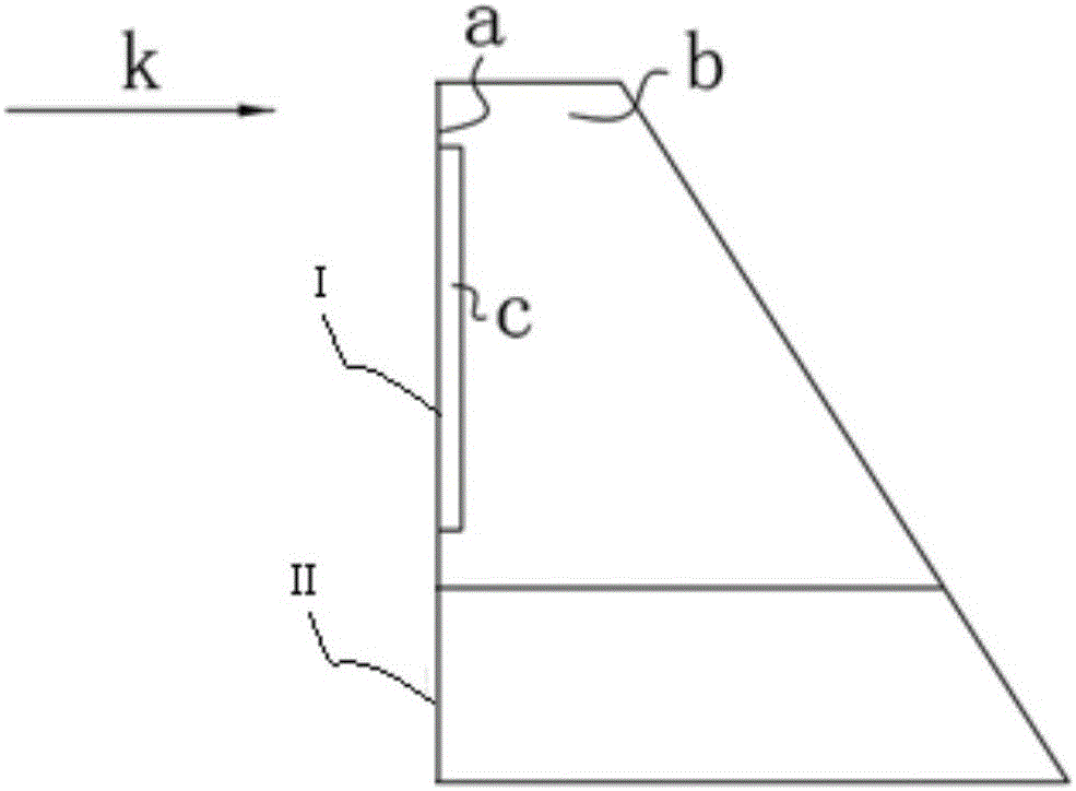
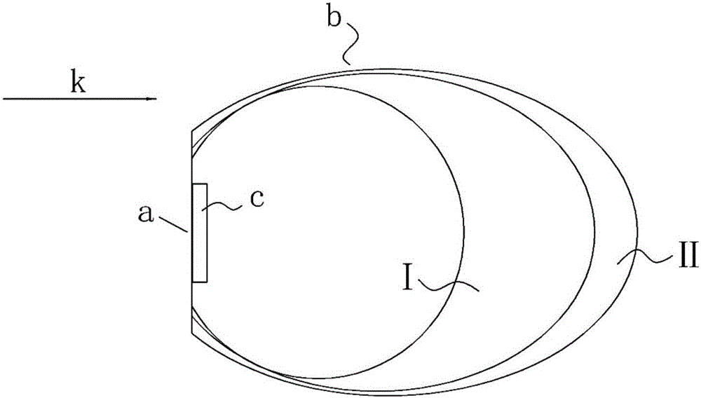
[0032] refer to Figure 1 ~ Figure 3 , an ice crystal detector probe, comprising a first section I and a second section II arranged sequentially from top to bottom, the first section I and the second section II are smoothly connected, wherein,

[0033] The outer surface of the first section I is set in a shape suitable for separating liquid water droplets and ice crystals in the airflow and accepting the impact of the ice crystals. In addition, the outer surface of the first section I includes a windward side a close to the airflow and a side facing away from the airflow, The leeward side b connected to the windward side a, the area of ​​the windward side a can meet the impact of ice crystals, and the windward side a can make the airflow flowing through the first section I generate a vortex on the windward side a, thereby taking away Liquid water in the airflow, the leeward side b is used to separate the boundary layer of the nearby airflow, so as to avoid water and ice accumu...

Embodiment 2

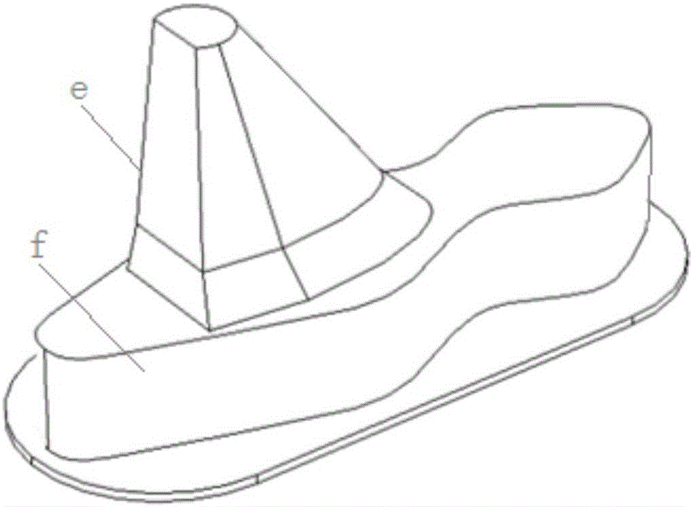
[0046] refer to Figure 4 ~ Figure 6 , the difference between this embodiment and embodiment 1 is mainly that the shape of the first section I is different. There are two windward surfaces a of the first section I in this embodiment, and each of the windward surfaces a is in line with the airflow The included angle of the direction k is a trapezoidal plane with an acute angle, and the included angle of the two windward surfaces a is also an acute angle;

[0047] The leeward surface b of the first section I is a cone-like surface, and it is smoothly connected with the windward surface a. It has a certain streamline shape and is smoothly connected with the windward surface a, so that the influence of the probe on the environmental flow field can be reduced

[0048] The top surface of the first section I presents a drop-like plane.

[0049] According to another aspect of the present invention, there is also provided a detector for complex icing conditions, including the above-me...


PUM


Abstract

The invention belongs to the field of aircrafts, and discloses an ice crystal detector probe and a complex icing condition detector. The ice crystal detector probe comprises a first section and a second section arranged in sequence from top to bottom; the first section and the second section are in smooth connection; the outer surface of the first section is in a shape suitable for separating liquid droplets from ice crystals in airflow and bearing impact of the ice crystals; a heating device and a plurality of fine particle impact sensors are installed inside the first section; and the second section is a heat insulation layer so as to avoid heat exchange between the first section and external probe installation equipment. The complex icing condition detector comprises the ice crystal detector probe and an icing detector probe. Liquid water in airflow does not generate obvious impact on the windward side of the probe, the ice crystals generate pulse impact on the windward side of the icing detector probe, and therefore the ice crystals and the liquid water droplets are distinguished and accurate detection of icing of the ice crystals can be achieved.

Description

technical field [0001] The invention belongs to the field of aircraft, and more specifically relates to an ice crystal detector probe and a complex icing condition detector including the probe. Background technique [0002] In the field of aircraft icing safety protection, ice crystals refer to particles with a median mass dimension (MMD) in the range of 50-200 microns (equivalent spherical size) formed by freezing water. The threat of ice crystal particles to flight is much more serious than that of rain. When an aircraft encounters an ice crystal cloud, it is easy to produce dry ice. Once ice accumulation occurs during flight, the aerodynamic performance of the aircraft will deteriorate, and the streamline shape will also be damaged. The roughness increases greatly, which increases the frontal resistance, reduces the lift and thrust, affects the stability of the aircraft, makes it difficult to maneuver, and in serious cases will cause an aircraft crash. The height of seri...

Claims


Application Information

Patent Timeline
Patent Type & Authority Applications(China)
IPC IPC(8): B64D15/20G01V9/00G01D21/02
CPCB64D15/20G01D21/02G01V9/00
Inventor 叶林陈欣星桂康葛俊锋
Owner HUAZHONG UNIV OF SCI & TECH
Learn More