Electromagnetic arresting device for deck landing or landing of aircraft

An electromagnetic and aircraft technology, applied in the direction of parking devices, etc., can solve the problems of large mass, low reliability, and complex structure of the landing assistance and arresting system, and achieve the effect of simple structure, high reliability, and small volume

Active Publication Date: 2016-11-09
HARBIN INST OF TECH
View PDF8 Cites 19 Cited by
  • Summary
  • Abstract
  • Description
  • Claims
  • Application Information

AI Technical Summary

Problems solved by technology

[0005] The purpose of the present invention is to solve the problems of large mass, large volume, complex structure and low reliability in the existing landing aid arresting system, and proposes an aircraft landing or landing electromagnetic arresting device

Method used


Image

  • Electromagnetic arresting device for deck landing or landing of aircraft
  • Electromagnetic arresting device for deck landing or landing of aircraft
  • Electromagnetic arresting device for deck landing or landing of aircraft

Examples


specific Embodiment approach 1

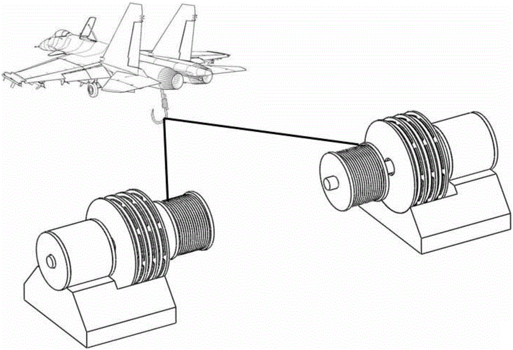
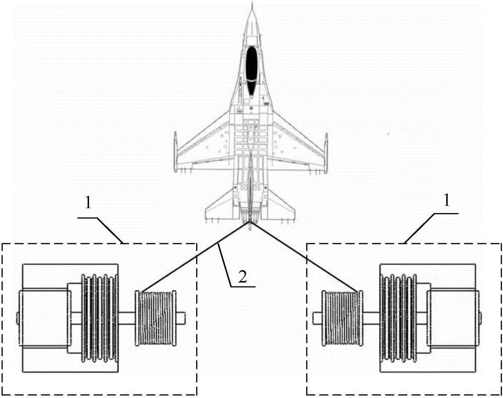
[0023] Specific implementation mode one: combine Figure 1 to Figure 3 To illustrate this embodiment, the aircraft landing or landing electromagnetic arresting device described in this embodiment includes two rotating electromagnetic arresters 1 with the same structure and an arresting cable 2;

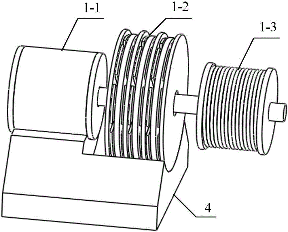
[0024] The rotary electromagnetic arrester 1 includes a rotary motor 1-1, a rotary eddy current brake 1-2, an arresting cable drum 1-3 and a motor drive controller, a rotary motor 1-1, a rotary eddy current brake 1-2 and an arresting cable The cable drum 1-3 share a rotating shaft, and the control signal output end of the motor drive controller is connected with the control signal input end of the rotating motor 1-1;

[0025] Two rotating electromagnetic arresters 1 are symmetrically arranged around the aircraft landing runway, and the two ends of the arresting cable 2 are respectively wound on the two arresting cable drums 1-3.

[0026] The working principle of the electromagnetic a...

specific Embodiment approach 2

[0027] Specific implementation mode two: combination figure 2 , Figure 4 and Figure 5 Describe this embodiment. This embodiment is a further limitation of the aircraft landing or landing electromagnetic arresting device described in Embodiment 1. In this embodiment, the rotary eddy current brake 1-2 is a multi-layer disc structure, including N+1 layers of stators and N layers of rotors, N is a positive integer, the stators and rotors are alternately distributed along the axial direction, forming a total of 2N layers of air gaps, and the axial length of each layer of air gaps is equal;

[0028] The stator includes a disk-shaped magnetic yoke plate and multiple permanent magnets, and the multiple permanent magnets are evenly distributed along the circumferential direction on the surface of the magnetic yoke plate;

[0029] The rotor is disc-shaped.

[0030] Such as figure 2 As shown, the casing of the rotating electrical machine 1-1 and the stator of the rotating eddy cu...

specific Embodiment approach 3

[0031] Specific implementation mode three: combination Figure 6 to Figure 8 Describe this embodiment. This embodiment is a further limitation of the aircraft landing or landing electromagnetic arresting device described in Embodiment 2. In this embodiment, the N-layer rotor adopts any one of the following three structures, two or three kinds;

[0032] The first structure: the rotor adopts a low-resistivity non-magnetic conductor plate (that is, a conductor plate, represented by A);

[0033] The second structure: the rotor adopts a magnetic material plate (that is, a magnetic plate, represented by B);

[0034] The third structure: the rotor includes two low-resistivity non-magnetic conductor plates and a disc-shaped magnetic conducting plate, and the two conducting plates are bonded on both sides of the magnetic conducting plate respectively (that is, the combination of the conducting plate and the magnetic conducting plate, denoted by C).

[0035] When the N rotors all ado...


PUM


Abstract

The invention discloses an electromagnetic arresting device for deck landing or landing of an aircraft and relates to an electromagnetic arresting system. The problems that an existing landing assisting and arresting system is large in weight and size, complicated in structure, low in reliability and the like are solved. The device comprises two rotary electromagnetic arresters of the same structure, and an arresting cable. Each rotary electromagnetic arrester comprises a rotary motor, a rotary eddy current retarder brake, an arresting cable drum and a motor driven controller, wherein the rotary motor, the rotary eddy current retarder brake and the arresting cable drum share one rotary shaft. The two rotary electromagnetic arresters are arranged symmetric with an aircraft landing runway as the center, and the two ends of the arresting cable are wound on the two arresting cable drums correspondingly. The electromagnetic arresting device adapts to deck landing or landing of a carrier aircraft.

Description

technical field [0001] The invention relates to an electromagnetic arresting system, which is suitable for the landing or landing of aircraft carriers. Background technique [0002] At present, the carrier-based aircraft landing-assisted arresting system on the aircraft carrier mainly uses arresting cables. Due to the very high flight speed, when the carrier-based aircraft is landing on the ship, the deck length of the aircraft carrier is far from meeting the landing glide distance, so the resistance of the arresting cable must be used to make it land smoothly. [0003] The traditional arresting cable system uses a hydraulic arresting device, which has the disadvantages of many moving parts, heavy system weight, large instantaneous impact force, and low reliability. In addition, in order to prevent the arresting load from exceeding the body strength or the braking force of the hydraulic arresting device during landing, the hydraulic arresting device has strict requirements ...

Claims


Application Information

Patent Timeline
Patent Type & Authority Applications(China)
IPC IPC(8): B64F1/02
CPCB64F1/02
Inventor 张赫寇宝泉金银锡张鲁陈雯
Owner HARBIN INST OF TECH
Why Eureka
Try Eureka