Three-dimensional active suspension type spacecraft microgravity stimulation device

A space vehicle and microgravity simulation technology, which is applied to the simulation device of space navigation conditions, transportation and packaging, space navigation equipment, etc., can solve problems such as the inability to complete the three-dimensional space movement experiment of space vehicles, achieve no time limit, reduce The effect of device weight and large simulation space

Active Publication Date: 2016-11-09
HARBIN INST OF TECH
View PDF6 Cites 24 Cited by
  • Summary
  • Abstract
  • Description
  • Claims
  • Application Information

AI Technical Summary

Problems solved by technology

[0005] In order to solve the problem that the existing space vehicle microgravity ground simulation method is limited to two-dimensional free movement of the space vehicle and cannot complete the three-dimensional movement experiment of the space vehicle, the present invention further provides a three-dimensional active suspension type space vehicle microgravity simulation device

Method used


Image

  • Three-dimensional active suspension type spacecraft microgravity stimulation device
  • Three-dimensional active suspension type spacecraft microgravity stimulation device

Examples


specific Embodiment approach 1

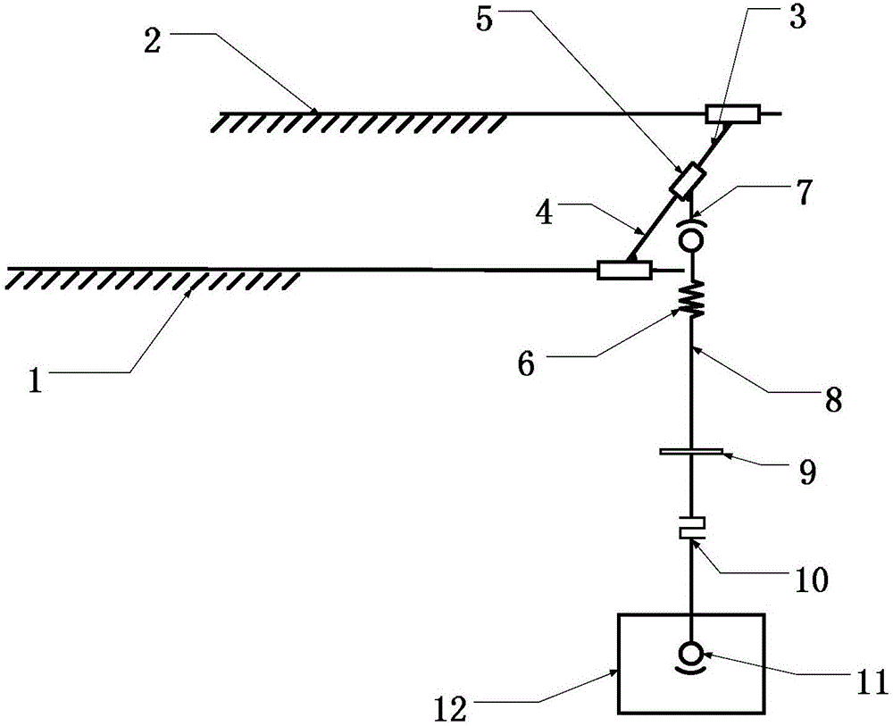
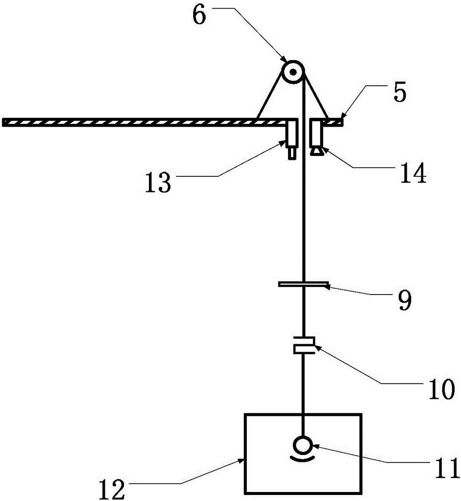
[0013] Specific implementation mode one: as Figure 1~2 As shown, the three-dimensional active suspension space vehicle microgravity simulation device of this embodiment includes a frame 1, an X-direction linear guide rail 4, an X-direction follow-up platform 5, a torque motor and a reel 6, an angle sensor 13, a laser ranging Sensor 14, sling hinge point 7, sling 8, plane mirror 9, tension sensor 10, ball bearing 11, two Y direction linear guide rails 2 and two Y direction follow-up platforms 3, the lower end of frame 1 is fixed on On the ground, two Y-direction linear guide rails 2 are horizontally and parallelly installed on the upper part of the frame 1, and each Y-direction linear guide rail 2 is provided with a Y-direction follow-up platform 3, and the two Y-direction follow-up platforms 3 are connected There is an X-direction linear guide rail 4, an X-direction follow-up platform 5 is arranged on the X-direction linear guide rail 4, a torque motor and a reel 6 are arrang...

specific Embodiment approach 2

[0016] Specific implementation mode two: as figure 1 with figure 2 As shown, the angle sensor 13 in this embodiment is a PSD angle sensor. With such a design, the optical circuit for measuring the spatial vertical angle of the sling 8 is formed with the plane reflector 9 installed in the vertical direction of the sling 8, so as to realize non-contact high-precision measurement of the spatial vertical angle of the sling. Other components and connections are the same as those in the first embodiment.

specific Embodiment approach 3

[0017] Specific implementation mode three: as figure 1 with figure 2 As shown, the X-direction servo platform 5 in this embodiment is a motor-driven servo platform. So designed to provide active tracking of the X-direction motion of the suspended spacecraft. Other compositions and connections are the same as those in Embodiment 1 or 2.


PUM


Abstract

The invention provides a three-dimensional active suspension type spacecraft microgravity stimulation device and relates to a spacecraft microgravity stimulation device. The invention solves the problem that the present spacecraft microgravity ground-based simulation method is only limited to the two-dimensional free motion of the spacecraft and cannot be adopted for finishing the motion experiment of the three-dimensional space of the spacecraft. Two Y-directional linear guide rails are horizontal and are mounted on the upper surface of a frame in parallel; a Y-directional servo platform is arranged on each of the Y-directional linear guide rails; an X-directional linear guide rail is connected between the two Y-directional servo platforms; an X-directional servo platform is arranged on the X-directional linear guide rail; a torque motor and a reel are arranged on the X-directional servo platform; an angle sensor and a laser ranging sensor are mounted on the lower end face of the X-directional servo platform; a sling hinge point is arranged on the X-directional servo platform; the upper end of the sling is wound on the reel; a plane reflector and a tension sensor are mounted on the sling from top to bottom; a ball bearing is arranged at the lower end of the sling. The three-dimensional active suspension type spacecraft microgravity stimulation device is applied to spacecraft microgravity stimulation.

Description

technical field [0001] The invention relates to a space vehicle microgravity simulation device, in particular to a three-dimensional active suspension type space vehicle microgravity simulation device. Background technique [0002] Space vehicles work in the microgravity environment of the outer space, and the outer space is different from the gravitational field on the earth's surface. When carrying out physical experiments of spacecraft on the ground, it is necessary to simulate the microgravity environment in space, that is, to apply compensation force to the spacecraft to offset the influence of surface gravity. Specifically, the motion function verification and kinematic algorithm verification of the spacecraft should be carried out during the completion of the experimental development stage, and the function of the spacecraft and the motion accuracy of the spacecraft should be tested at the final assembly yard. The above process must be completed on the ground, and th...

Claims


Application Information

Patent Timeline
Patent Type & Authority Applications(China)
IPC IPC(8): B64G7/00
CPCB64G7/00
Inventor 刘振于海涛项升丁亮李楠高海波邓宗全
Owner HARBIN INST OF TECH
Why Eureka
Try Eureka