Floating support device for on-ground gravity unloading of aerospace optical load

A technology of gravity unloading and space optics, which is applied in the fields of precision machinery and space optics, can solve problems such as low imaging quality and changes in the pose of optical components, and achieve the effects of reducing the size of the device, offsetting the maximum deformation, and reducing unloading residuals

Active Publication Date: 2019-01-11
CHANGCHUN INST OF OPTICS FINE MECHANICS & PHYSICS CHINESE ACAD OF SCI
View PDF5 Cites 7 Cited by
  • Summary
  • Abstract
  • Description
  • Claims
  • Application Information

AI Technical Summary

Problems solved by technology

[0009] The invention aims to overcome the defects that the large-aperture, long-focus space optical telescope is installed and adjusted on the ground, and the internal deformation caused by gravity will rebound after the gravity is released in the orbit, resulting in changes in the position and orientation of optical components and low imaging quality.

Method used


Image

  • Floating support device for on-ground gravity unloading of aerospace optical load
  • Floating support device for on-ground gravity unloading of aerospace optical load
  • Floating support device for on-ground gravity unloading of aerospace optical load

Examples


Embodiment Construction

[0041] In order to make the object, technical solution and advantages of the present invention clearer, the present invention will be further described in detail below in conjunction with the accompanying drawings and specific embodiments. It should be understood that the specific embodiments described here are only used to explain the present invention, but not to limit the present invention.

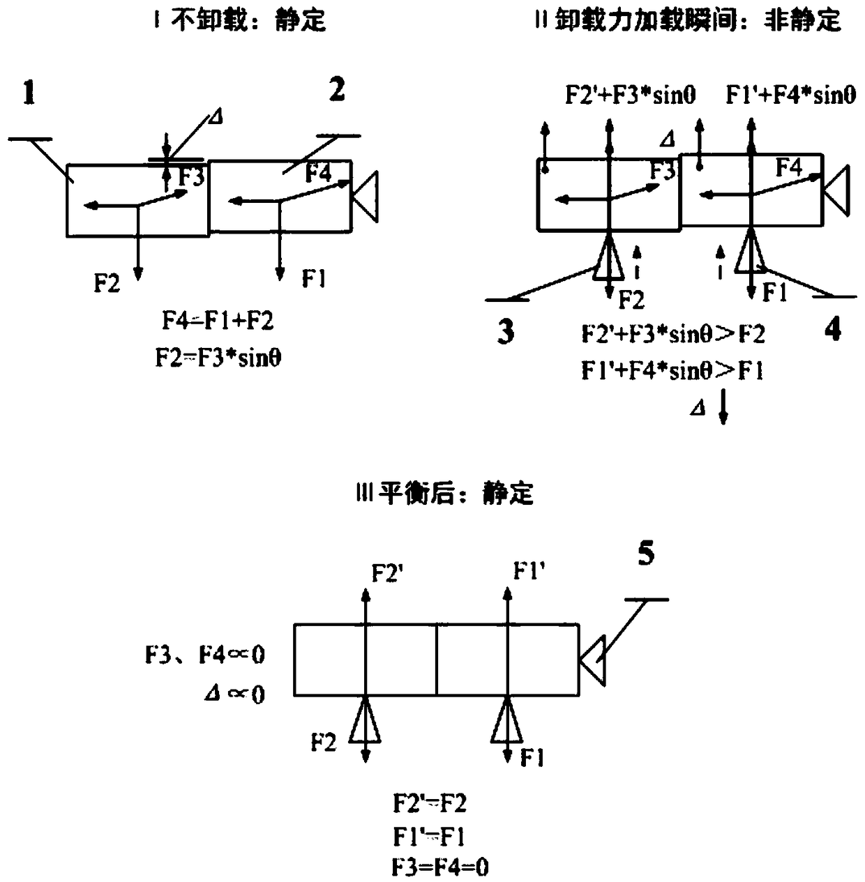
[0042] first reference figure 1 , indicating the working principle of the present invention, while the unloading device provides a given unloading force, it needs to release the six degrees of freedom of the unloading force vector at the same time, and ensure that the unloading direction of the applied unloading force is always parallel to the direction of the gravity vector, and The loading and unloading force does not change with the change of the loading position, and does not change with the change of the space load attitude. In addition, the gravity unloading device should be as ...


PUM


Abstract

The invention relates to the field of precision machinery and aerospace optical technology, and in particular discloses a floating support device for on-ground gravity unloading of aerospace optical load, comprising an unloading base, and multiple sets of gravity unloading devices arranged on the unloading base. The gravity unloading devices are fixedly arranged under the optical load. The floating support device also comprises multiple sets of fixed support devices arranged on the back of the optical load. Gravity unloading in the direction of the gravity vector can be achieved by the gravityunloading devices, thereby offsetting the maximum deformation introduced by the gravity of the large optomechanical structure, and significantly alleviating the effect brought by the inconsistency ofsky-earth mechanics on the accuracy of on-ground installation and alignment as well as the quality of on-orbit imaging of aerospace optical loading. Therefore, the invention provides basic image quality for on-ground pre-installation and alignment as well as active optical correction for high-sensitivity optical components. In addition, through on-ground gravity unloading, the unnecessary designof the large aperture optical load optomechanical structure and the launching cost can be greatly reduced, and the use efficiency of the aerospace vehicle can be improved.

Description

technical field [0001] The invention relates to the technical fields of precision machinery and space optics, in particular to a floating support mechanism for large-diameter space optical loads to be unloaded by gravity on the ground. Background technique [0002] A space optical telescope is a type of space optical payload mounted on a satellite platform for imaging and measuring various astronomical phenomena in the universe, or for push-broom or staring observation of ground objects. For example, the well-known Hubble Telescope and WordView earth observation satellites are equipped with such space optical telescopes for optical imaging of various astronomical phenomena or ground scenes. All kinds of space optical loads ultimately work in the microgravity environment of space, but the installation and testing of optical loads are carried out on the ground, and gravity will accompany the entire installation and testing process. This leads to the inconsistency between the ...

Claims


Application Information

Patent Timeline
Patent Type & Authority Applications(China)
IPC IPC(8): G02B7/183
CPCG02B7/183
Inventor 何煦杨雪张晓辉董吉洪
Owner CHANGCHUN INST OF OPTICS FINE MECHANICS & PHYSICS CHINESE ACAD OF SCI
Why Eureka
Try Eureka