Optical glass rod material drawing device

An optical glass and rod technology, applied in glass manufacturing equipment, glass production, manufacturing tools, etc., can solve the problems of inability to draw glass into sub-rods or optical fibers with circular cross-section, difficulty, easy crystallization and fringes, etc. , to achieve the effect of avoiding direct use, reducing shape requirements, and stable high temperature performance

Active Publication Date: 2016-11-09
HUBEI NEW HUAGUANG NEW INFORMATION MATERIALS CO LTD
View PDF4 Cites 6 Cited by
  • Summary
  • Abstract
  • Description
  • Claims
  • Application Information

AI Technical Summary

Problems solved by technology

But there are problems: First, some lanthanide glass, such as H-ZLaF**, H-ZF**, etc., are prone to crystallization and streaks, so they need to be milled or even cut before they can be used when producing strips. One-time bar drawing operation is complicated and difficult, and it can no longer be used as mother bar after milling or cutting, resulting in a low yield rate of primary bar utilization, which is not suitable for bar production; the second is how to transform the stock bar products into the market The required bar products are also a problem that needs to be solved urgently

Method used


Image

  • Optical glass rod material drawing device
  • Optical glass rod material drawing device
  • Optical glass rod material drawing device

Examples


Embodiment 1

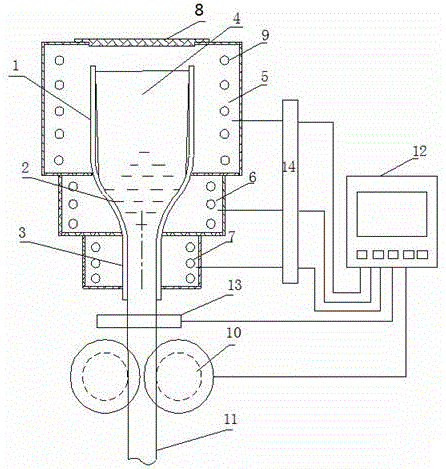
[0020] Example 1 as figure 1 , figure 2 shown. An optical glass rod drawing device of the present invention comprises a softening crucible 1, a viscosity adjusting crucible 2 and a rod forming die 3 connected from top to bottom, and a rod diameter detection device is arranged below the rod forming die 3 13. A bar pulling device 10 is installed below the bar diameter detection device 13, and also includes a temperature control device 14 and a microcomputer control device 12. Softening crucible 1, viscosity adjusting crucible 2 and bar forming mold 3 are equipped with softening crucible auxiliary furnace 5, viscosity adjusting crucible auxiliary furnace 6 and bar forming mold auxiliary furnace 7, softening crucible auxiliary furnace 5, viscosity adjusting crucible auxiliary furnace The furnace 6 and the auxiliary furnace 7 of the bar forming mold are respectively equipped with 9 groups of independent heating rods, and the 9 groups of three independent heating rods are respect...

Embodiment 2

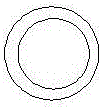
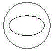
[0027] Example 2 as image 3 shown. In Example 2, the cavity cross section of the softening crucible 1 is circular, and the cavity cross section of the bar forming die is oval.

Embodiment 3

[0028] Example 3 as Figure 4 shown. In Example 3, the cavity cross section of the softening crucible 1 is circular, and the cavity cross section of the bar forming mold is rectangular.


PUM

PropertyMeasurementUnit
Diameteraaaaaaaaaa

Abstract

The invention provides an optical glass rod material drawing device and belongs to the technical field of secondary forming of optical glass. The problem of low master rod material utilization rate caused by secondary rod material surface defects at present is mainly solved. The optical glass rod material drawing device is mainly characterized by comprising a softening crucible, a viscosity adjusting crucible and a rod material forming mold which are connected from top to bottom to form a whole. Heating rods are arranged in a heat-preserving furnace body outside the softening crucible, the viscosity adjusting crucible and the rod material forming mold. A rod material traction device is arranged below the rod material forming mold. The rod material forming mold is smaller than the softening crucible in cavity cross section area. The surfaces of the inner cavities of the softening crucible, the viscosity adjusting crucible and the rod material forming mold are continuously smooth. A charging port is formed in the top of the softening crucible. The optical glass rod material drawing device has the advantages that glass master rod materials which have forming defects on the surfaces or are not suitable for direct secondary rod material production can be directly drawn into required sub-rod materials and the product yield is improved, and is mainly used for secondary draw-forming of optical glass rod materials.

Description

technical field [0001] The invention belongs to the technical field of secondary molding of optical glass. It specifically relates to a bar material secondary forming device, which is mainly used for secondary drawing forming of optical glass bar material. Background technique [0002] At present, many optical element processing manufacturers are gradually turning to the use of optical preforms to produce circular optical element blanks, which can not only avoid the investment of equipment and personnel in the spheronization process after cutting the strips, but also reduce the material waste generated in the spheronization process. At the same time, the preparation of optical fibers also needs to use optical preforms, so the demand for optical preforms is also increasing. But there are problems: First, some lanthanide glass, such as H-ZLaF**, H-ZF**, etc., are prone to crystallization and streaks, so they need to be milled or even cut before they can be used when producing...

Claims


Application Information

Patent Timeline
IPC IPC(8): C03B37/03C03B37/025
CPCC03B37/025C03B37/0253C03B37/03Y02P40/57
Inventor 胡弦张欣瑞王拓李杰徐华峰
Owner HUBEI NEW HUAGUANG NEW INFORMATION MATERIALS CO LTD
Why Eureka
Try Eureka