Supercharge Your Innovation With Domain-Expert AI Agents!

System and method for sweeping accumulated dust through steam produced during garbage pyrolysis after waste heat is recovered

A water vapor and garbage technology, which is applied to the system field of purging radiant tubes to accumulate dust, can solve the problems of dust on the surface of the radiant tubes, waste, and affect the heating capacity of the radiant tubes, and achieve the effect of restoring the heating capacity and avoiding the loss of heat.

Pending Publication Date: 2016-11-09
SHENWU TECH GRP CO LTD
View PDF0 Cites 0 Cited by
  • Summary
  • Abstract
  • Description
  • Claims
  • Application Information

AI Technical Summary

Problems solved by technology

During this process, the water vapor generated in the drying area is not effectively utilized, and the amount of water vapor is large, which is about 30% to 50% of the garbage mass, causing great waste
In addition, the radiant tube has a phenomenon of ash on the surface, which cannot be removed in time, which affects the heating capacity of the radiant tube

Method used


Image

  • System and method for sweeping accumulated dust through steam produced during garbage pyrolysis after waste heat is recovered
  • System and method for sweeping accumulated dust through steam produced during garbage pyrolysis after waste heat is recovered
  • System and method for sweeping accumulated dust through steam produced during garbage pyrolysis after waste heat is recovered

Examples


Embodiment 1

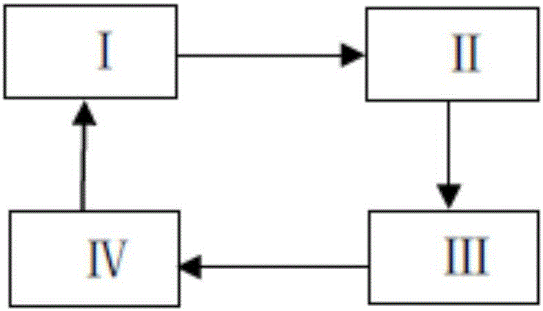
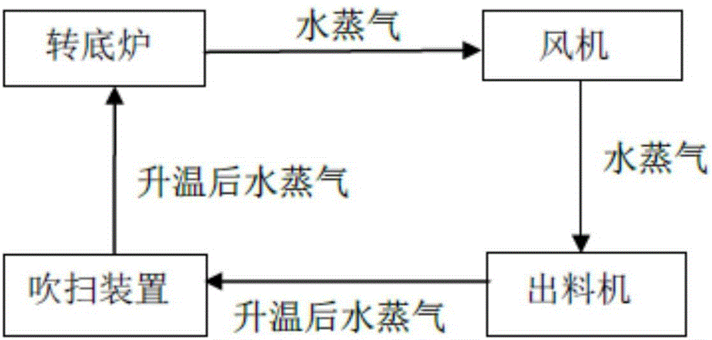
[0061] The garbage raw materials are transported to the rotary hearth furnace for drying and pyrolysis, and the pressure in the drying zone is maintained to be 5Pa higher than the pressure in the feeding zone and the pyrolysis zone respectively, and the water vapor temperature at the gas outlet of the drying zone is 120-180°C. The water vapor is transported to the indirect cooling screw discharger, and the temperature is raised to 450°C. The heated water vapor is transported to the purging device, and then the heated water vapor is sprayed into the surface of the radiant tube in the rotary hearth furnace by the purging device to remove the ash accumulated on it.

Embodiment 2

[0063] The steps in this example are the same as those in Example 1. The pressure in the drying zone is maintained to be 8Pa higher than the pressure in the feed zone and the pyrolysis zone respectively. The water vapor temperature at the gas outlet of the drying zone is 180-230°C, and the temperature of the water vapor after heating is 500°C. , other conditions are the same as in Example 1.

Embodiment 3

[0065] The steps in this example are the same as those in Example 1. The pressure in the drying zone is maintained to be 10 Pa higher than the pressure in the feed zone and the pyrolysis zone. The water vapor temperature at the gas outlet of the drying zone is 230-400°C, and the temperature of the water vapor after heating is 500°C. , other conditions are the same as in Example 1.


PUM


Abstract

The invention relates to a system and method for sweeping accumulated dust through steam produced during garbage pyrolysis after waste heat is recovered. The system comprises a rotary hearth furnace, draught fans, a discharging machine and a sweeping device. The rotary hearth furnace is provided with a rotary circular furnace bottom used for placement and pyrolysis of garbage, and a radiant pipe is arranged on the upper portion of a hearth of the rotary hearth furnace. The method comprises the steps that the garbage is conveyed onto the furnace bottom of the rotary hearth furnace to be dried and pyrolyzed, steam and pyrolytic carbon are obtained, the pyrolytic carbon and the steam carry out heat exchange in the discharging machine, and after the temperature of the steam is raised, the steam is conveyed onto the radiant pipe in the rotary hearth furnace through the sweeping device to sweep the accumulated dust on the surface of the radiant pipe. By means of the system and method, energy substances produced in the process of pyrolyzing the garbage in the rotary hearth furnace can be effectively utilized, the temperature-raised high-purity steam is used for sweeping the accumulated dust on the surface on the radiant pipe in the system, and the loss of heat is avoided.

Description

technical field [0001] The invention relates to the field of solid waste resource treatment, in particular to a system and method for purging ash accumulated on radiant tubes after recovering waste heat from pyrolysis charcoal by using water vapor generated by pyrolyzing waste in a rotary hearth furnace. Background technique [0002] With the rapid development of my country's economy, the speed of urbanization continues to accelerate, people's living standards continue to improve, and the output of solid waste, especially urban domestic waste, is also increasing, causing serious pollution to the environment. Under the influence of the concept of sustainable development, the development, application and industrialization of solid waste harmless, reduction and resource treatment technologies will face a broad prospect. Therefore, the research on solid waste treatment technology has become another research hotspot after the research on wastewater and waste gas treatment. Among...

Claims


Application Information

Patent Timeline
IPC IPC(8): C10B53/00C10B43/02
CPCY02P20/129C10B53/00C10B43/02
Inventor 陶进峰吴道洪
Owner SHENWU TECH GRP CO LTD
Features
  • R&D
  • Intellectual Property
  • Life Sciences
  • Materials
  • Tech Scout
  • Unparalleled Data Quality
  • Higher Quality Content
  • 60% Fewer Hallucinations
Learn More