Method for increasing recovery ratio of tight oil reservoir through CO2 foam huff and puff

A tight oil and oil recovery technology, applied in the fields of fluid production, earthwork drilling, wellbore/well components, etc., can solve the problems of reduced production energy, waste of resources, gas channeling, etc., and achieve the effect of improving oil recovery.

Inactive Publication Date: 2016-11-09
CHINA UNIV OF PETROLEUM (EAST CHINA)
View PDF4 Cites 23 Cited by
  • Summary
  • Abstract
  • Description
  • Claims
  • Application Information

AI Technical Summary

Problems solved by technology

However, compared with low-permeability reservoirs, tight oil reservoirs have lower permeability, tight oil matrix and fracture heterogeneity differences are greater, depletion recovery energy decreases rapidly, and CO 2 The throughput effect is limited, and effective flow control is required
If only a single use of CO 2 Huff and puff to improve recovery of tight oil reservoirs prone to CO 2 Gas channeling cannot effectively control the fluidity of the gas, and cannot play the role of plugging and regulating displacement, and the effect is not obvious enough
If water flooding is used alone, the fractures can only be filled but cannot spread to the matrix, and oil recovery cannot be performed, which is a waste of resources

Method used


Image

  • Method for increasing recovery ratio of tight oil reservoir through CO2 foam huff and puff
  • Method for increasing recovery ratio of tight oil reservoir through CO2 foam huff and puff

Examples


Embodiment Construction

[0007] Technical scheme of the present invention is as follows:

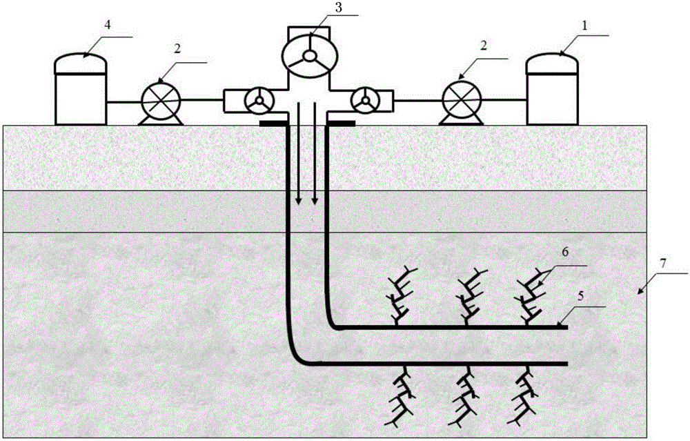
[0008] A tight oil reservoir CO 2 The method for improving recovery by foam stimulation includes the following steps:

[0009] (1) High pressure CO 2 Slug injection: inject 0.01PV to 0.1PV of CO under reservoir conditions 2 The slug is injected into the tight oil reservoir through the wellbore, filling the fractured fractures;

[0010] (2) Surfactant aqueous solution slug injection: The surfactant aqueous solution is fully mixed and then injected into the tight oil layer. The volume of the injected aqueous solution is the same as the CO 2 The volume ratio is 1:2 to 1:1, and the mass concentration of the surfactant aqueous solution is 0.1 to 1.0%;

[0011] (3) Diffusion of soaked wells: After injecting the aqueous surfactant solution into the tight oil layer, the wells are soaked, and the pressure changes during the soaked wells are recorded. During the soaked wells, the CO 2 Mass transfer and diffusion from...


PUM


Abstract

The invention relates to a method for increasing the recovery ratio of a tight oil reservoir through CO2 foam huff and puff. The method comprises the steps that high-pressure CO2 is injected into the fractured tight oil reservoir for slugging, cracks are mainly filled with CO2 for soaking, and crude oil enters the cracks from the matrix under the actions such as extraction, volume expansion and dissolution and viscosity reduction; and after the pressure of a wellhead is stable, a well is opened for production, in the formation seepage process, CO2 makes contact with a surface active agent aqueous solution to generate foam, the CO2 foam displaces the crude oil so that the crude oil can flow from the cracks to a shaft, and finally the crude oil is recovered to the ground. According to the method, no foam is generated in the CO2 injection process, and the situation that the generated CO2 foam displaces the crude oil to the deep position of the oil reservoir is prevented; and in the recovery process, the CO2 makes contact with the surface active agent aqueous solution so that the foam can be generated in the stratum, through the mechanisms that the CO2 foam conducts oil cleaning in the cracks and the fluidity of CO2 is effectively controlled, more crude oil in the cracks can be displaced into the shaft, and the recovery ratio of the tight oil reservoir is increased.

Description

technical field [0001] The invention relates to a tight oil reservoir CO 2 The invention relates to a method for improving recovery by foam huffing and puffing, which belongs to the technical field of oil and gas field development engineering. Background technique [0002] The increasingly serious environmental problems have prompted people to pay more attention to CO 2 impact on the environment, but also on the CO 2 High expectations are placed on the development of capture technology. The Chinese government has also made a commitment: by 2020, CO2 per unit of GDP 2 Emissions will be reduced by 40-45% on the basis of 2005. Using CO 2 Oil flooding enables CO 2 Capture, storage, utilization, etc., to reduce CO in the atmosphere 2 content. [0003] Tight oil refers to oil stored in tight sandstone, tight carbonate rock and other reservoirs with matrix permeability less than or equal to 0.2mD (air permeability less than 2mD). Single wells in tight oil reservoirs genera...

Claims


Application Information

Patent Timeline
Patent Type & Authority Applications(China)
IPC IPC(8): E21B43/22
CPCE21B43/164
Inventor 李松岩李兆敏刘己全李宾飞鹿腾张超冀国伟
Owner CHINA UNIV OF PETROLEUM (EAST CHINA)
Why Eureka
Try Eureka