A low-pressure manifold device for continuous supply of liquid nitrogen under pressure
A technology of low-pressure manifolds and liquid nitrogen, which is applied in the field of oil and gas field exploration and development, can solve the problems of field equipment confusion, discontinuous construction, and many low-pressure pipelines, so as to save construction sites, reduce construction operation risks, and meet operation requirements. Effect
- Summary
- Abstract
- Description
- Claims
- Application Information
AI Technical Summary
Problems solved by technology
Method used
Image

Examples
Embodiment 1
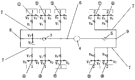
[0021] This embodiment provides a low-pressure manifold device for continuous supply of liquid nitrogen under pressure, such as figure 1 As shown, it includes a main line 6 and a branch line 7. The branch line 7 includes multiple liquid inlet lines and multiple liquid discharge lines. The multiple liquid inlet lines are connected in parallel to one end of the main line 6 to form a liquid inlet end. 8. Multiple drain lines are connected in parallel to the other end of the main line 6 to form a drain end 9; each liquid inlet line is connected to a liquid nitrogen tanker 1, and each drain line is connected to a liquid nitrogen tanker Pump truck 2.
[0022] A liquid nitrogen filter 3 , a flowmeter 4 and a pressure gauge 5 are connected in series on the main line 6 from the liquid inlet 8 to the liquid discharge 9 . The pipelines between are also connected with a safety valve and a vent valve.
[0023] According to the layout of the well site, place the low-pressure manifold devi...
Embodiment 2
[0026] This example is refined on the basis of Example 1, and a specific implementation scheme is given. In this example, the main line 6 and the branch line 7 are arranged in a T-shaped arrangement. There are six liquid inlet lines, and three lines are respectively arranged on both sides near the liquid inlet end 8 of the main line, and the six liquid inlet lines are connected in parallel to the liquid inlet end 8 of the main line 6; Two lines are arranged on both sides of the discharge end 9 of the main line, and the four discharge lines are connected in parallel to the discharge end 9 of the main line 6 .
[0027] The main pipeline 6 and the branch pipeline 7 adopt a T-shaped design, and all low-pressure pipelines are made of stainless steel 304, and all necessary fittings ensure that the pipeline system is safe and has no pressure relief, meeting the construction requirements of a displacement of 2000L / min.
[0028] Each inlet pipeline is connected in series with an inlet ...
Embodiment 3
[0037] This embodiment is further improved on the basis of the previous two embodiments. In this embodiment, both the main line 6 and the branch line 7 are installed on a bottom skid frame, and four corners of the bottom skid frame are respectively welded with lifting lugs. The skid frame is all welded with standard profiles, and the lifting lugs are welded at the four corners of the skid frame for equipment hoisting.
[0038] In this embodiment, the whole device is concentrated on a bottom skid frame, so that when the equipment is used, it appears neat and orderly, and will not cause the phenomenon of many and complicated low-pressure pipelines on the liquid nitrogen construction site and confusion of on-site equipment, and , The application and transportation of the overall equipment are also more convenient.
PUM
| Property | Measurement | Unit |
|---|---|---|
| Temperature tolerance | aaaaa | aaaaa |
Abstract
Description
Claims
Application Information
 - Generate Ideas
- Intellectual Property
- Life Sciences
- Materials
- Tech Scout
- Unparalleled Data Quality
- Higher Quality Content
- 60% Fewer Hallucinations
Browse by: Latest US Patents, China's latest patents, Technical Efficacy Thesaurus, Application Domain, Technology Topic, Popular Technical Reports.
© 2025 PatSnap. All rights reserved.Legal|Privacy policy|Modern Slavery Act Transparency Statement|Sitemap|About US| Contact US: help@patsnap.com