Pressure reduction device capable of recycling fluid energy
A decompression device and fluid pressure technology, which is applied in the direction of the valve's fluid energy absorption device, valve device, safety device, etc., to achieve the effects of easy manufacture, convenient and wide use, and improved energy recovery efficiency
- Summary
- Abstract
- Description
- Claims
- Application Information
AI Technical Summary
Problems solved by technology
Method used
Image


Examples
Embodiment 1
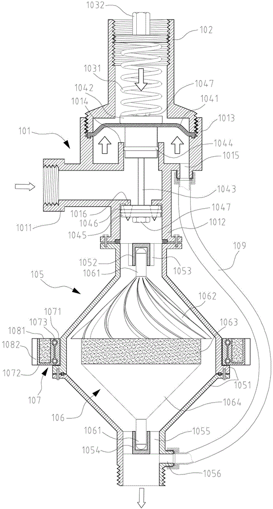
[0034] Such as figure 1 , figure 2 As shown, the pressure reducing device capable of recovering fluid energy shown in this embodiment is actually a pressure reducing valve capable of recovering fluid energy. Its components include: valve body 101, valve cover 102, pressure spring 1031, pressure regulating bolt 1032, Rubber diaphragm 1041, diaphragm pressure plate 1042, valve stem 1043, seal ring 1044, piston 1045, piston ring 1046, nut 1047, turbine housing 105, turbine rotor 106, rolling bearing 107, permanent magnet 1081, gear 1082, and conduit 109.
[0035] The valve body 101 is composed of a fluid inlet section 1011, a fluid outlet section 1012, a hydraulic cylinder cylinder body 1013, a valve stem sleeve 1014, a hydraulic cylinder interface 1015 and a spray needle 1016. The hydraulic cylinder body 1013 is arranged in the upper part of the fluid inlet section 1011; the spray needle 1016 is arranged at the junction of the fluid inlet section 1011 and the fluid outlet section 1...
Embodiment 2
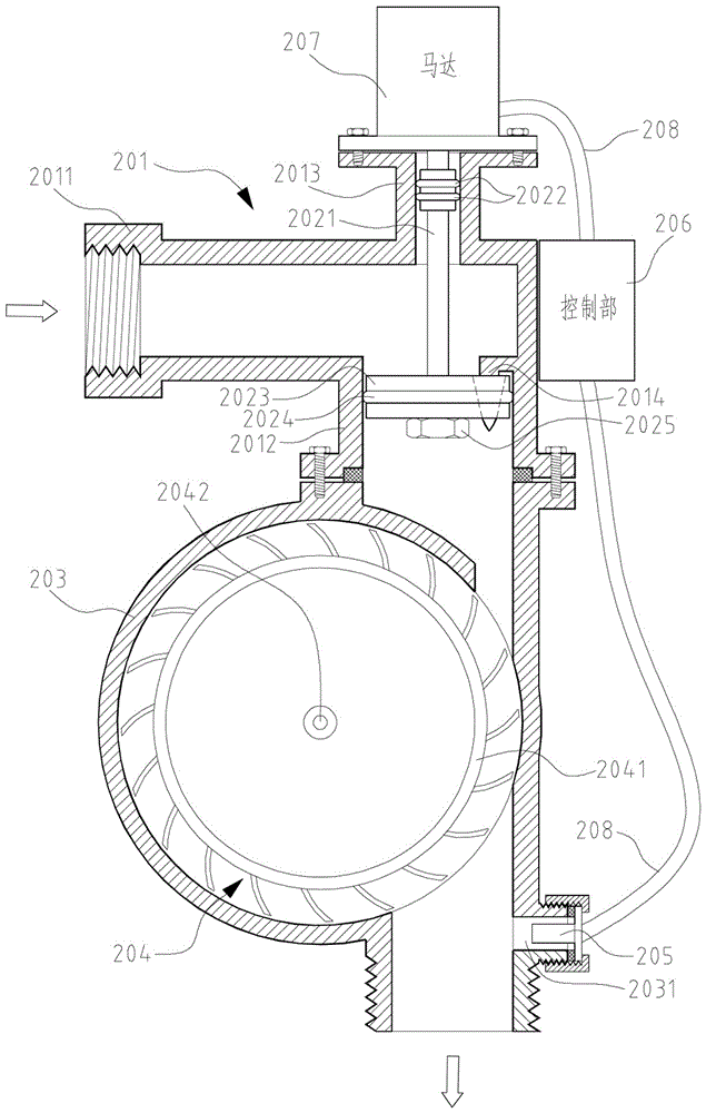
[0048] Such as Figure 3 ~ Figure 5 As shown, the pressure reducing device capable of recovering fluid energy shown in this embodiment includes: valve body 201, valve stem 2021, sealing ring 2022, piston 2023, piston ring 2024, nut 2025, turbine housing 203, turbine rotor 204 , Pressure sensor 205, control unit 206, motor 207, cable 208.
[0049] The valve body 201 is composed of a fluid inlet section 2011, a fluid outlet section 2012, a valve stem sleeve 2013 and a spray needle 2014. The valve stem sleeve 2013 is arranged at the upper part of the fluid inlet section 2011; the spray needle 2014 is arranged at the junction of the fluid inlet section 2011 and the fluid outlet section 2012.
[0050] The piston 2023 is sleeved on the lower part of the valve rod 2021 and is locked on the valve rod 2021 by a nut 2025. The side of the piston 2023 is also fixedly sleeved with a piston ring 2024; the middle of the valve rod 2021 is fixedly sleeved with a sealing ring 2022; The motor 207 i...
Embodiment 3
[0057] This embodiment is basically the same as Embodiment 2. The only difference from Embodiment 2 is that this embodiment also includes an excitation device and a generator; in addition, compared with the control unit 206, the control unit in this embodiment also It can control the excitation device. Hereinafter, the present embodiment will be described in detail, and the same reference numerals are given to the same structural members as in the second embodiment, and the description thereof is omitted.
[0058] In this embodiment, one end of the shaft 2042 protruding from the turbine housing 203 is fixedly connected to the rotor of the generator, so that the turbine rotor 204 drives the generator rotor to rotate, and the mechanical energy of the turbine is converted into electrical energy output. The generator is electrically connected with the excitation device, the excitation device is electrically connected with the control unit, and the excitation device is supplied with e...
PUM
 Abstract
Description
Claims
Application Information
 - R&D
- Intellectual Property
- Life Sciences
- Materials
- Tech Scout
- Unparalleled Data Quality
- Higher Quality Content
- 60% Fewer Hallucinations
Browse by: Latest US Patents, China's latest patents, Technical Efficacy Thesaurus, Application Domain, Technology Topic, Popular Technical Reports.
© 2025 PatSnap. All rights reserved.Legal|Privacy policy|Modern Slavery Act Transparency Statement|Sitemap|About US| Contact US: help@patsnap.com