Two-dimensional taper roller piston pump

A technology of tapered roller and piston pump, applied in the field of hydraulic pump and hydraulic motor, can solve the problems of rapid cylinder temperature rise, large moment of inertia, displacement limitation, etc., to reduce contact stress, simplify the overall structure, and improve work efficiency. Effect

Active Publication Date: 2016-11-09
河南航天流体控制技术有限公司
View PDF5 Cites 12 Cited by
  • Summary
  • Abstract
  • Description
  • Claims
  • Application Information

AI Technical Summary

Problems solved by technology

There are many relatively moving parts inside, high requirements on material and machining accuracy, sensitive to oil pollution, high requirements and costs for processing, use, and maintenance, and expensive; the cylinder rotates with the transmission shaft, and the moment of inertia is large, resulting in The response speed of start, stop, and speed regulation is slow, which is not conducive to controlling the output flow of the pump through speed regulation; there are many friction pairs in the cylinder body, and the cylinder temperature rises faster under high-speed rotation, and the valve plate, plunger (piston) The wear and tear of other parts directly affects the service life and durability of the pump
In addition, due to the limitation of the working principle of the plunger (piston) pump itself, each plunger (piston) can only achieve one oil suction and one oil discharge when the transmission shaft rotates one revolution. Design the flow distribution mechanism to complete the switching of oil suction and discharge in the working chamber
[0004] The lubricating system of the existing plunger pump is connected with the infusion system, and the transported liquid is used as a lubricant. This structure is only suitable for transporting oil, and is not suitable for use in water medium environments.

Method used


Image

  • Two-dimensional taper roller piston pump
  • Two-dimensional taper roller piston pump
  • Two-dimensional taper roller piston pump

Examples


Embodiment Construction

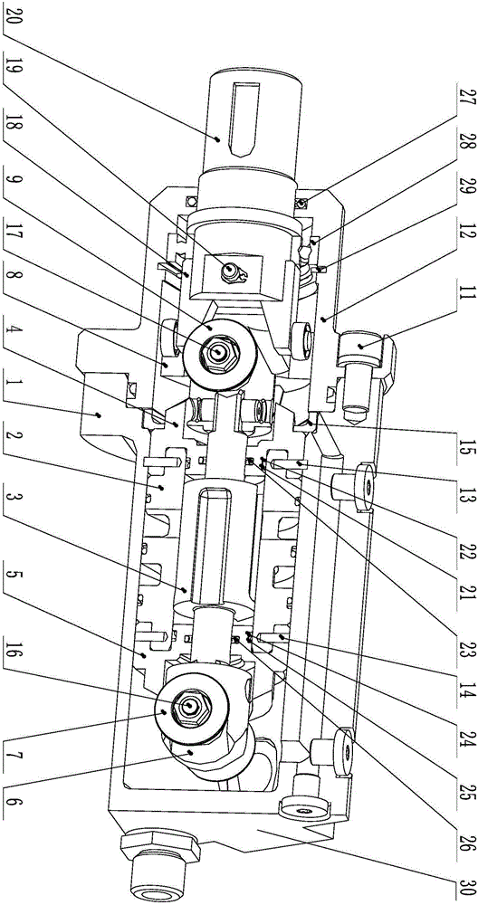
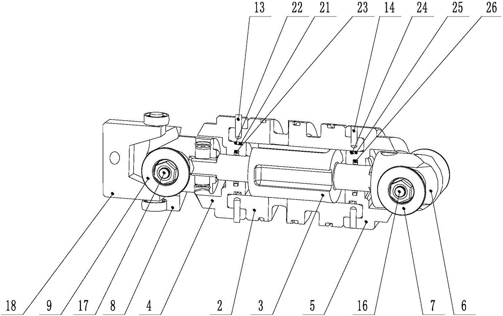
[0065] Referring to the accompanying drawings, the two-dimensional tapered roller piston pump includes a pump body 1 with a liquid suction hole and a liquid discharge hole. The pump body 1 is provided with a pump unit, and the pump unit is connected to the motor.

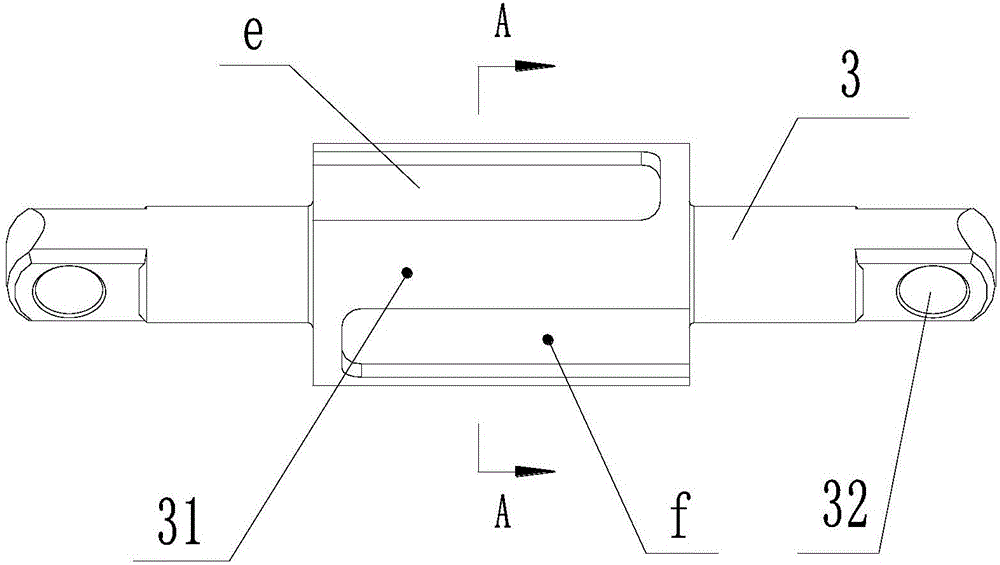
[0066] The pump unit includes a cylinder 2 fixed in the pump body 1, a piston 3 is arranged in the cylinder 2, the central axis of the cylinder 2 coincides with the central axis of the piston 3, and both ends of the piston 3 are equipped with a drive piston 3 axially The trigger device that moves to cause the volume of the working chamber to change, and the trigger devices at both ends of the piston 3 drive the piston 3 to move in the opposite direction;

[0067] The working chamber includes a left chamber and a right chamber respectively located at both ends of the cylinder body. A shoulder 31 is provided in the middle of the piston 3. The left end surface of the shoulder 31 and the guide rail 4 on the left side enc...


PUM


Abstract

A two-dimensional taper roller piston pump comprises a pump body, wherein a liquid sucking hole and a liquid draining hole are formed in the pump body, a pump unit is arranged in the pump body, and the pump unit is connected with a motor; the pump unit comprises a cylinder body fixed in the pump body, a piston is arranged in the cylinder body, and a central shaft of the cylinder body is coincided with a central shaft of the piston; and the two ends of the piston are both provided with triggering devices which drive the piston to axially move, causing the capacity variation of a working cavity, and the movement directions that the triggering devices at the two ends of the piston drive the piston are opposite. A guide rail is in linear contact with a taper roller, so that rolling contact area is increased, contact stress is reduced, slip is effectively avoided, and the service life of contact components is also prolonged. Besides, a lubricating cavity and the working cavity are airtight and separated, so that oil-water separation is realized. The two-dimensional taper roller piston pump is suitable for an oil medium as well as a water medium, so that the use range is enlarged.

Description

technical field [0001] The invention relates to a two-dimensional tapered roller piston pump, belonging to hydraulic pumps and hydraulic motors in the field of fluid transmission and control. Background technique [0002] The plunger (piston) pump uses a plunger (piston) and a cylinder block as the main working components. When the plunger (piston) reciprocates in the plunger (piston) hole of the cylinder, the volume of the closed working volume chamber composed of the plunger (piston) and the cylinder changes, and the suction and discharge process is completed. According to the different arrangements of the plunger (piston) in the cylinder, the plunger (piston) pump is divided into two categories: radial type and axial type. [0003] The traditional common axial plunger (piston) pump relies on the reciprocating movement of the plunger (piston) in the cylinder to change the volume of the sealed working chamber to achieve oil suction and pressure. There are many relatively ...

Claims


Application Information

Patent Timeline
Patent Type & Authority Applications(China)
IPC IPC(8): F04B9/02F04B17/03F04B53/18F04B53/14
CPCF04B9/02F04B17/03F04B53/14F04B53/18F16H25/12
Inventor 阮健金丁灿申屠胜男李胜童成伟孟彬
Owner 河南航天流体控制技术有限公司
Why Eureka
Try Eureka