Rotation compressor and refrigerating cycle device with same

A technology of rotary compressors and compression mechanisms, applied in compressors, compressors, rotary piston machinery, etc., can solve the problems of increasing cost and environmental protection, increasing the amount of sealed oil, increasing the amount of oil discharged in the refrigeration cycle, and avoiding wear and tear failure, ensure reliable operation, and reduce the effect of sealing oil volume

Active Publication Date: 2016-11-09
GUANGDONG MEIZHI COMPRESSOR +1
View PDF7 Cites 7 Cited by
  • Summary
  • Abstract
  • Description
  • Claims
  • Application Information

AI Technical Summary

Problems solved by technology

However, increasing the amount of sealed oil will increase the amount of oil discharged in the refrigeration cycle. Not only will the amount of oil (oil level) in the compressor fluctuate, but the amount of refrigerant sealed in the lubricating oil will also increase.
In other words, increasing the amount of sealed oil not only does not solve the problem at all, but also is not conducive to the miniaturization of the compressor, and also has hidden dangers of increasing costs and environmental protection

Method used


Image

  • Rotation compressor and refrigerating cycle device with same
  • Rotation compressor and refrigerating cycle device with same
  • Rotation compressor and refrigerating cycle device with same

Examples


Embodiment 1

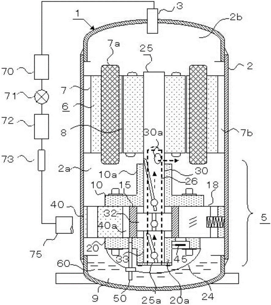
[0073] The design outline of the present invention, based on figure 1 Be explained. The single-cylinder rotary compressor 1 includes an inverter-type electric motor 6 (hereinafter referred to as motor 6) fixed to the inner peripheral wall of a sealed casing 2 and a compression mechanism 5, and the bottom of the sealed casing 2 (hereinafter referred to as casing 2) is constituted The oil storage tank 60 is equipped with lubricating oil 9 (hereinafter referred to as oil 9). The compression mechanism 5 is driven by the rotor 8 constituting the motor 6. The motor lower cavity 2a and the motor upper cavity 2b are high-voltage cavities divided by the motor 6 in the housing 2.

[0074] The compression mechanism 5 includes a cylinder 40 that is arc spot welded to the inner peripheral wall of the housing 2, a first bearing 10 that seals the compression chamber 40a of the cylinder 40 and is slidably fitted with the main shaft 30 of the crankshaft 25, and a first bearing 10 that is slidabl...

Embodiment 2

[0113] Image 6 with Figure 7 , Is to use the difference between the specific gravity of the refrigerant gas and the oil, so that the oil-containing refrigerant gas passing through the shaft hole 26 can selectively extend the time that the oil stays in the shaft hole 26, or treat the shaft hole 26 as a simple oil storage cavity the design of. In addition, after the oil retention amount in the shaft center hole 26 is saturated, the oil amount of the oil-containing refrigerant gas discharged to the motor lower cavity 2a does not change.

[0114] Image 6 , Fix the thin sleeve 26a to the air hole 30a in the shaft, and press the spiral plate 28 into the lower side of the hole 26 in the shaft. The oil-containing refrigerant gas flowing from the shaft end hole 25 a into the shaft center hole 26 is accelerated by the spiral plate 28. The oil having a specific gravity greater than the refrigerant gas rises along the inner wall of the shaft center hole 26, so the amount of oil passing t...

Embodiment 3

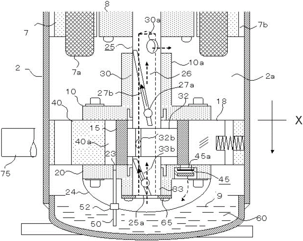
[0117] Figure 8 , A first muffler 14 is added to the first bearing 10 where the exhaust device 45 is arranged. The low-pressure refrigerant gas sucked into the compression chamber 40 a from the suction pipe 75 becomes a high-pressure oil-containing refrigerant gas, and is equally divided and discharged to the second muffler 24 and the first muffler 14.

[0118] The oil-containing refrigerant gas discharged into the first muffler 14 merges with the oil-containing refrigerant gas discharged into the second muffler 24 through the muffler communication hole 63. After that, it passes through the shaft hole 26 from the shaft end hole 25a, and is discharged from the shaft hole 30a. In the meantime, lubricate the sliding parts. In this embodiment, the oil groove 27b and the oil groove 33b are machined into the inner peripheral walls of the first bearing 10 and the second bearing 20, respectively.

[0119] Picture 9 In this case, even if the exhaust device 45 is arranged on the first be...


PUM


Abstract

The invention discloses a rotation compressor and a refrigerating cycle device with the rotation compressor. An electric motor and a compression mechanism portion are contained in a sealed shell of the rotation compressor. A suction pipe is arranged on the shell. An oil storage tank storing lubricating oil is arranged at the bottom of the shell. The compression mechanism portion comprises an air cylinder, a piston, a slide sheet, a crankshaft and bearings. The air cylinder is provided with a compression cavity. Refrigerant gas, containing oil, discharged from the compression cavity at least flows through a gas passageway arranged between the crankshaft and the bearings to be discharged into the shell. According to the rotation compressor, the oil discharge amount of the compressor is lowered, and on the basis that oil supply to the compression mechanism portion is sufficient, the seal oil amount of the compressor does not need to be increased.

Description

Technical field [0001] The invention relates to the field of refrigeration, and in particular to a rotary compressor and a refrigeration cycle device having the same. Background technique [0002] The existing rotary compressor uses a centrifugal oil supply pump that utilizes the rotation of the crankshaft to lubricate the crankshaft and pistons. However, centrifugal oil supply pumps used in rotary compressors such as air conditioners can cause a large amount of oil in the compressor caused by a large amount of oil discharged in various operation modes such as low-temperature starting, defrosting operation, and high-speed operation. The problem of lower surface height) and insufficient fuel supply pump volume have become the main cause of compressor failure. [0003] In order to improve the shortage of oil supply pump caused by the decrease of oil quantity (oil level), it is common sense to increase the sealing oil quantity of the compressor. Taking an air conditioner as an examp...

Claims


Application Information

Patent Timeline
Patent Type & Authority Applications(China)
IPC IPC(8): F04C18/356F04C29/02F04C29/06F25B1/04F25B31/00
CPCF04C18/3562F04C29/02F04C29/026F04C29/068F04C2240/50F25B1/04F25B31/004
Inventor 小津政雄宋鹏杰王玲
Owner GUANGDONG MEIZHI COMPRESSOR
Why Eureka
Try Eureka