Double-channel combustion heat exchanger

A combustion heat, dual-channel technology, applied in the direction of fluid heaters, lighting and heating equipment, etc., can solve the problems of difficulty in innovation breakthrough and technological improvement of the whole machine performance, difficulty in improving heat exchange efficiency, and unfavorable miniaturization development, etc., to achieve The effect of simple structure, long working length and wide heat exchange area

Inactive Publication Date: 2016-11-09
佛山耐美芯科技有限公司
View PDF6 Cites 1 Cited by
  • Summary
  • Abstract
  • Description
  • Claims
  • Application Information

AI Technical Summary

Problems solved by technology

These heat exchangers usually have only one set of heat exchange channels, so in the process of heating water and domestic hot water, multiple sets of heat exchangers are often required to work together (that is, a primary heat exchanger and a secondary (or multi-stage) heat exchanger are required. The combination of heat exchangers can meet the requirements of use), resulting in a more complex product structure, high production costs, not conducive to the development of miniaturization, difficult to improve heat exchange efficiency, and difficult to have innovative breakthroughs and technological improvements in the performance of the whole machine

Method used


Image

  • Double-channel combustion heat exchanger
  • Double-channel combustion heat exchanger
  • Double-channel combustion heat exchanger

Examples


Embodiment Construction

[0025] The present invention will be further described below in conjunction with the accompanying drawings and embodiments.

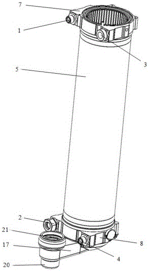
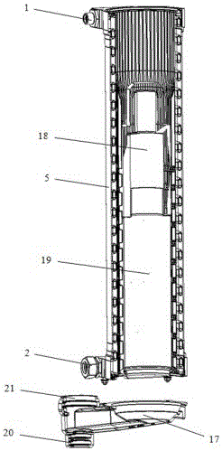
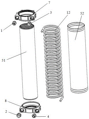
[0026] see Figure 1-Figure 6 , the double-channel combustion heat exchanger includes a cylindrical main body 5 composed of an inner cylinder 51 and an outer cylinder 52. The inner cylinder 51 is hollow inside and constitutes a combustion chamber 6 for combustion of gas and air mixture and makes high-temperature flue gas flow to There are two sets of heat exchange passages between the inner cylinder 51 and the outer cylinder 52 in the smoke exhaust channel conveyed below (that is, the heat exchange gap 15 described below); the lower end of the cylindrical body 5 is provided with a heating return water joint 2 and a cold water joint 4, The upper end of the cylindrical body 5 is provided with a hot water joint 1 and a heating water outlet joint 3. The first group of heat exchange channels 13 is connected between the heating return water joint 2 and the he...


PUM


Abstract

The invention relates to a double-channel combustion heat exchanger, comprising a barrel-shaped main body formed by an inner barrel and an outer barrel, wherein the interior of the inner barrel is hollow, and a combustion chamber used for burning mixture of gas and air and a smoke exhaust channel used for enabling high temperature flue gas to be conveyed downwards are formed in the inner barrel; two groups of heat exchange channels are arranged between the inner barrel and the outer barrel; the lower end of the barrel-shaped main body is provided with a heating return water connector and a cold water connector; the upper end of the barrel-shaped main body is provided with a hot water connector and a heating outlet water connector; the first group of heat exchange channel is connected between the heating return water connector and the heating outlet water connector; the second group of heat exchange channel is connected between the cold water connector and the hot water connector. The high temperature flue gas produced by the double-channel combustion heat exchanger is transmitted and discharged downwards from top to bottom, heating system water or domestic water in the heat exchange channels flows from bottom to top, heat exchange is carried out between the heating system water or the domestic water and the high temperature flue gas, and convection is formed since the combustion direction is opposite to the heat exchange direction; furthermore, the combustion chamber is in a long barrel shape, thus being longer in heat exchange length and larger in heat exchange area; therefore, the heat exchanger has very high heat exchange efficiency, and the heat exchange efficiency reaches up to 107% or more.

Description

technical field [0001] The invention relates to a double-channel combustion heat exchanger. Background technique [0002] After years of development in the wall-hung boiler industry, ordinary wall-hung boilers with atmospheric combustion have entered a technical bottleneck period. The obsolete technology is seriously difficult to innovate, with low energy efficiency and large emissions. Therefore, more and more wall-hung boiler manufacturers gradually realize that condensing wall-hung boilers are the commanding heights of technology and products that represent the development direction of the industry. The road to sustainable development of enterprises. [0003] As a high-end product of a fully premixed condensing wall-hung boiler, the heat exchanger is one of its core technologies and configurations. At present, there are mainly two types of mainstream heat exchangers on the market, one is a stainless steel coil condensing heat exchanger, and the other is One is a square ...

Claims


Application Information

Patent Timeline
IPC IPC(8): F24H9/18
CPCF24H9/1836
Inventor 欧敬欢
Owner 佛山耐美芯科技有限公司
Why Eureka
Try Eureka