Full distributed fiber displacement sensor based on fiber grating positioning

A technology of displacement sensor and optical fiber grating, applied in the direction of instruments, optical devices, measuring devices, etc., can solve the problems of difficult application, small range, large displacement measurement error, etc., and achieve the effect of high displacement sensitivity

Inactive Publication Date: 2016-11-09
SHIJIAZHUANG TIEDAO UNIV
View PDF6 Cites 0 Cited by
  • Summary
  • Abstract
  • Description
  • Claims
  • Application Information

AI Technical Summary

Problems solved by technology

However, these two types of sensors also have certain defects. The fiber grating displacement sensor detects the displacement through the wavelength movement reflected by the internal sensitive element fiber grating. It has complex structure design, small measuring range, and inability to directly obtain displacement data. It is used in practical engineering. difficulty
The fiber grating quasi-distributed displacement sensor and the Brillouin distributed displacement sensor obtain the structural displacement through the integral of the distributed strain of the structure, and the displacement measurement error is large

Method used


Image

  • Full distributed fiber displacement sensor based on fiber grating positioning
  • Full distributed fiber displacement sensor based on fiber grating positioning
  • Full distributed fiber displacement sensor based on fiber grating positioning

Examples


Embodiment 1

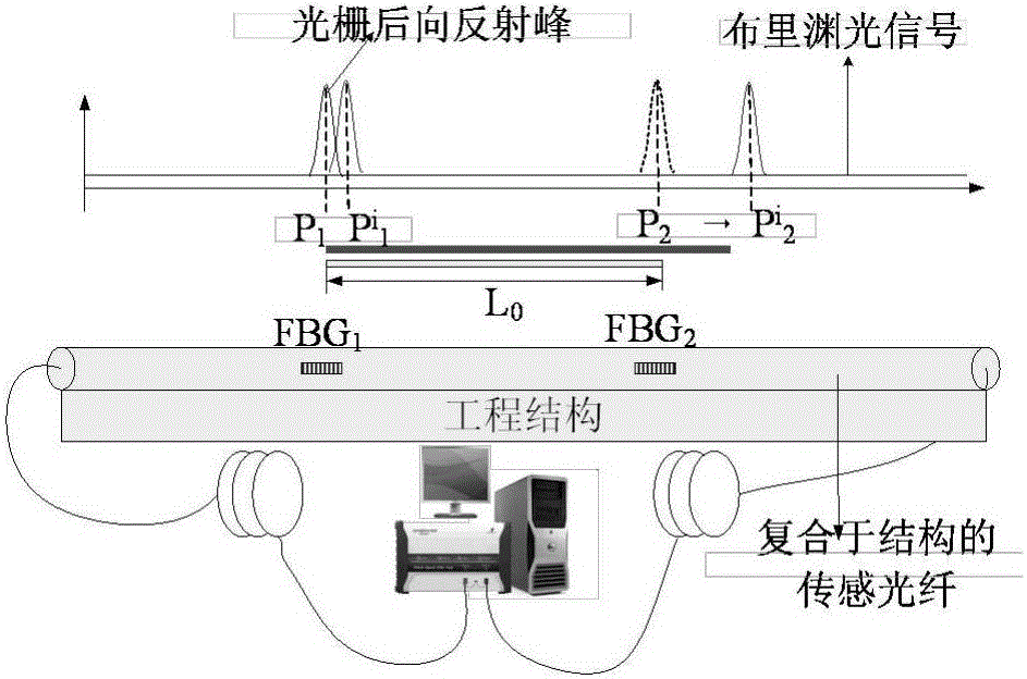
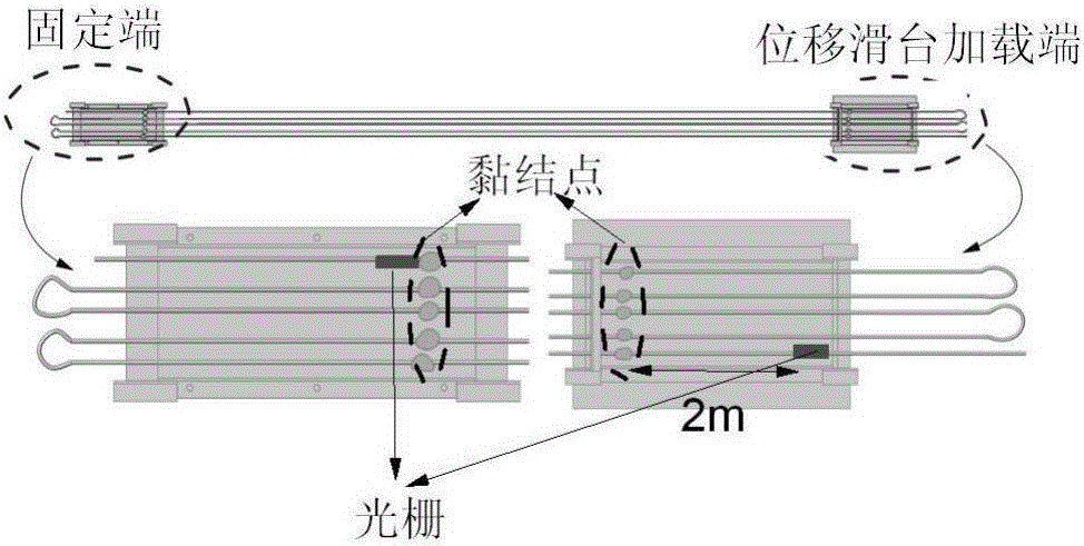
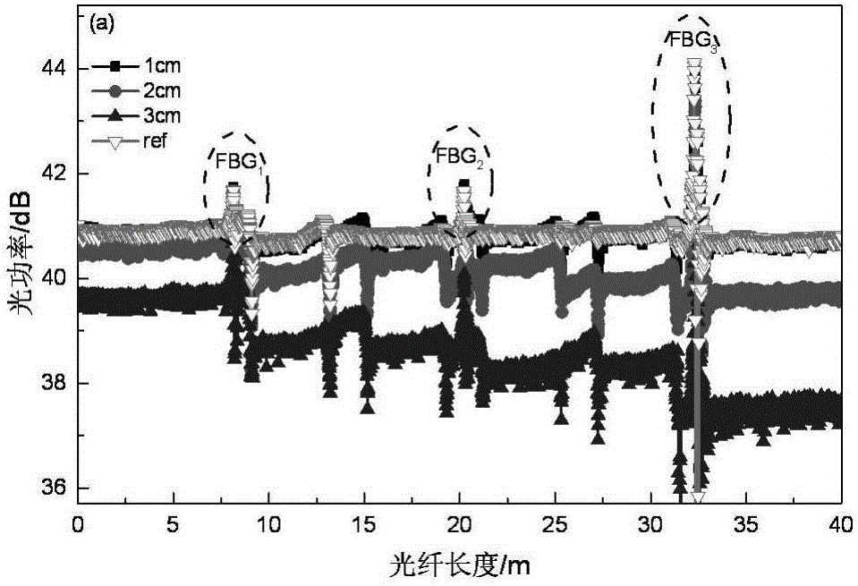
[0033] In Example 1, 1# displacement sensor is connected in series with 3 fiber gratings with different wavelengths, all of which are Bragg gratings, and their performance parameters are shown in Table 1. In the displacement loading experiment, due to the limitation of the laboratory space, the load length of the structure cannot be designed too large, but this factor is not affected in the actual project. In order to improve the displacement range and sensitivity coefficient of the displacement sensor, a multi-section bearing Carrier fiber. Among them, the 1# displacement sensor is equipped with 4 sections of 3.96m loaded optical fiber sections (all of which are tensioned optical fiber sections), and the displacement is applied through the displacement slide table. , 7575.8με), to ensure that the loading strain is less than the ultimate strain.

Embodiment 2

[0035] In order to increase the displacement and reduce the applied strain amplitude, the 2# displacement sensor in Example 2 is connected in series with two fiber gratings with different wavelengths, both of which are Bragg gratings, and their performance parameters are shown in Table 1. In the displacement loading experiment, the 2# displacement sensor is equipped with 5 sections of 5.0m loaded optical fiber sections (all of which are tensioned optical fiber sections), and the displacement is applied through the displacement slide table. The loading displacement is 0.5cm, 1cm, 1.5cm, 2cm, 2.5 cm (corresponding strains are 1000με, 2000με, 3000με, 4000με, 5000με), to ensure that the optical fiber does not debond during the tension process. During the experiment, the position of one end of the fixed fiber remains unchanged, and the other end is displaced by a displacement slide to achieve the purpose of changing the distance between the fiber gratings and realize the structural ...


PUM


Abstract

The invention relates to the technical field of fiber sensing, and especially relates to a full distributed fiber displacement sensor based on fiber grating positioning, for solving the technical problem of designing a full distributed fiber displacement sensor which has a large measurement range, does not require integration for displacement data, is simple in structure and is easily applied to a deep geotechnical engineering structure. The full distributed fiber displacement sensor comprises a full distributed sensing fiber, the full distributed sensing fiber is connected in series with more than two fiber gratings, the fiber gratings are taken as position indicators, and the position of one of the fiber gratings is fixed.

Description

technical field [0001] The invention relates to the technical field of optical fiber sensing, in particular to a fully distributed optical fiber displacement sensor based on optical fiber grating positioning. Background technique [0002] Displacement monitoring is an important means to evaluate the deep underground deformation of landslides, and has been widely used in the stability prediction of dams, rock masses and slopes. The development of the country's economic construction has put forward higher requirements for shape monitoring technology, and there is an urgent need for shape monitoring technology with large range, high precision, and good stability, especially with the large investment in railways, highways, and water conservancy projects in my country in recent years. It is very important to monitor the stability problems of dam body and slope deformation in real time and accurately. [0003] Displacement sensors include inductive displacement sensors, capacitive...

Claims


Application Information

Patent Timeline
Patent Type & Authority Applications(China)
IPC IPC(8): G01B11/02
CPCG01B11/02
Inventor 李剑芝徐龙祥李义强侯跃敏孙宝臣
Owner SHIJIAZHUANG TIEDAO UNIV
Why Eureka
Try Eureka