Eureka AIR delivers breakthrough ideas for toughest innovation challenges, trusted by R&D personnel around the world.

A fixture for obtaining agmi effect and a method for obtaining agmi effect based on the fixture

An effect and fixture technology, applied in the field of AGMI effect generation, can solve problems such as low sensitivity, increased power consumption, complex AGMI effect method, etc., and achieve the effect of strong operability, low cost, and low energy consumption

Active Publication Date: 2019-03-15
ZHEJIANG NORMAL UNIVERSITY
View PDF8 Cites 0 Cited by
  • Summary
  • Abstract
  • Description
  • Claims
  • Application Information

AI Technical Summary

Problems solved by technology

[0008] The technical problem to be solved by the present invention is to provide a fixture for obtaining the AGMI effect and a method for obtaining the AGMI effect based on the fixture. Realized, but adding bias will significantly increase power consumption, and the method of obtaining the AGMI effect is too complicated and the problem of low sensitivity

Method used


Image

  • A fixture for obtaining agmi effect and a method for obtaining agmi effect based on the fixture
  • A fixture for obtaining agmi effect and a method for obtaining agmi effect based on the fixture
  • A fixture for obtaining agmi effect and a method for obtaining agmi effect based on the fixture

Examples


Embodiment 1

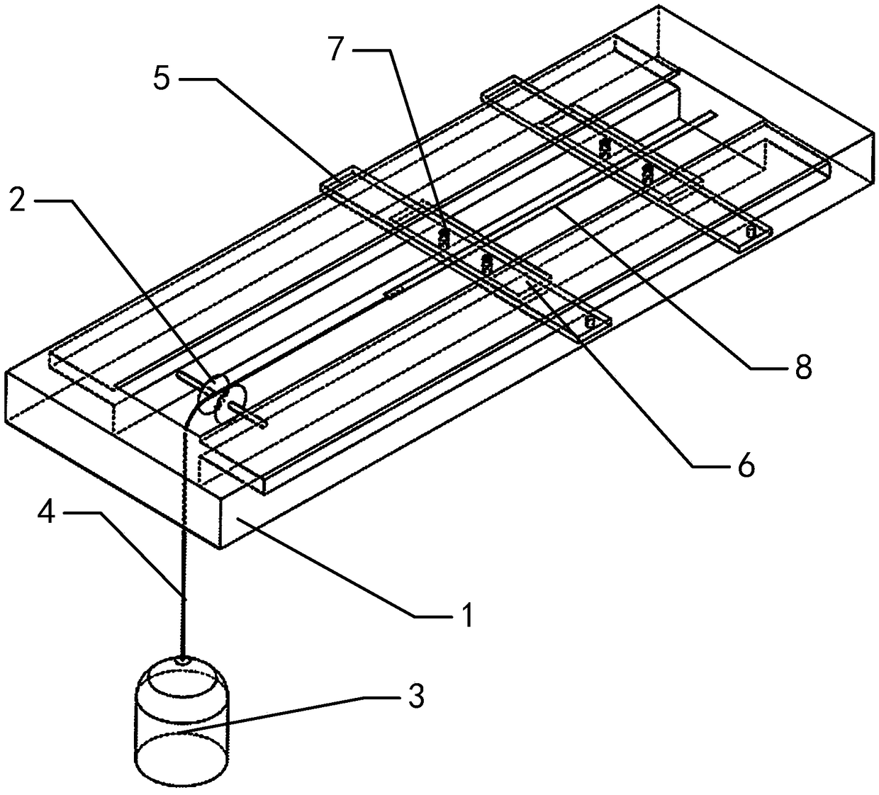
[0033] Such as figure 1 As shown, the present embodiment proposes a fixture for obtaining the AGMI effect. The fixture includes a bottom plate 1, a pulley 2, a weight 3 and two groups of splints. The bottom plate 1 is a rectangular plate structure, and the two groups of splints and The short sides of the bottom plate 1 are arranged on the bottom plate 1 parallel to each other for clamping the amorphous material 8. The center of the bottom plate 1 is provided with a strip-shaped through hole parallel to its long side, and at one end of the strip-shaped through hole A rotatable pulley 2 is arranged between the two side walls of the pulley. The plane on which the pulley 2 rotates is a vertical plane. Connect, and connect the other end with weight 3.

[0034] The amorphous material 8 is clamped by two sets of splints, and the weight 3 is used to apply stress to the amorphous material 8, which can effectively achieve different current annealing on an amorphous material 8, thereby ...

Embodiment 2

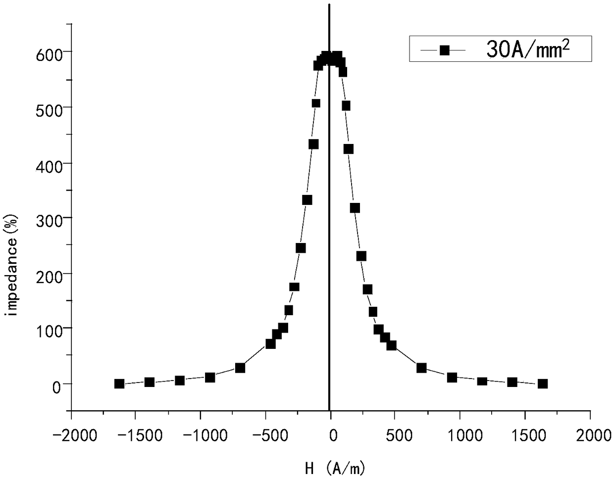
[0040] Such as image 3 The current density shown is 30A / mm 2 The GMI curve of a material annealed by current for 10 minutes has a maximum impedance ratio of 588.1%, and its impedance curve is symmetrical about zero magnetic field, which makes its sensitivity insensitive near zero magnetic field; Figure 4 The current density shown is 40A / mm 2 In the GMI curve of current annealing, due to the precipitation of the hard magnetic phase, the impedance ratio is greatly reduced, and it is no longer symmetrical about the zero magnetic field, but the linearity near the zero magnetic field reaches 99%. The method proposed in this embodiment is to select the advantages of both to achieve the AGMI effect of zero magnetic field linear response. The specific implementation process is as follows:

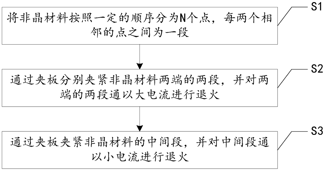
[0041] Such as figure 2 As shown, the method is realized through the following steps:

[0042] S1. Divide the amorphous material into N points in a certain order, with a section between eve...


PUM

PropertyMeasurementUnit
Sensitivityaaaaaaaaaa

Abstract

The invention relates to a clamp for obtaining an AGMI effect and a method for obtaining the AGMI effect based on the same, and relates to the field of AGMI effect generation. The problems that due to the fact that at present, an external coil or a biasing permanent magnet needs to be adopted for obtaining the AGMI effect to generate a bias field, however power consumption is obviously increased when bias is added, and an existing method for obtaining the AGMI effect is excessively complex and low in sensitivity are solved. Two clamping plates are adopted for clamping a non-crystalline material, a weight is adopted for applying stress on the non-crystalline material, different current annealing can be effectively achieved on the non-crystalline material, and in this way, the AGMI effect can be obtained.

Description

technical field [0001] The present invention relates to the field of AGMI effect generation. Background technique [0002] The GMI effect (magnetic effect) is used as a means to study new magnetic sensors due to its high sensitivity and fast response characteristics, but the GMI effect is not sensitive near the zero magnetic field, so the detection of the GMI sensor near the zero field is fatal. blind spot. AGMI (Asymmetric Magnetic Effect) can provide highly sensitive linear response near zero magnetic field, which can make up for the deficiency of GMI magnetic sensor near zero magnetic field, and meet the design and development requirements of sensors with high sensitive linear response to weak magnetic field. [0003] The generation of AGMI effect can be summarized into three methods: [0004] (1) AGMI effect produced by current bias. The AGMI effect produced by DC bias was first discovered to be formed by adding a DC bias field to an AC drive current in a twisted thre...

Claims


Application Information

Patent Timeline
Patent Type & Authority Patents(China)
IPC IPC(8): G01N3/04
CPCG01N3/04
Inventor 范晓珍李素梅马云何兴伟方允樟
Owner ZHEJIANG NORMAL UNIVERSITY
Why Eureka
Eureka Blog
Learn More