
A test device and method for obtaining forming limit diagrams under complex loading conditions

A technology of forming limit diagram and test device, which is applied in the direction of measuring device, testing material ductility, instrument, etc., can solve the problems of short interval, error-prone, complicated calculation process, etc., to save test time, shorten test cycle, Avoid the effects of the experimental process

Active Publication Date: 2018-12-14
ANHUI UNIVERSITY OF TECHNOLOGY
View PDF7 Cites 0 Cited by
  • Summary
  • Abstract
  • Description
  • Claims
  • Application Information

AI Technical Summary

Problems solved by technology

[0006] 1. There is no definite theoretical system to determine the forming limit diagram of a certain sheet during theoretical calculation. The calculation process is complex and error-prone, and before the calculation, it is necessary to obtain some required material performance values ​​through material performance experiments, such as processing Hardening index, thickness anisotropy coefficient, etc.
[0007] 2. The test method needs to process sheets of different sizes, that is, a variety of samples are required
The method to realize the complex loading path is essentially divided into two tests, that is, pre-deformation and then bulging. The two tests are not carried out at the same time, and the aging time after sheet metal processing is not considered, and most of the parts are formed at one time or at intervals. The time is very short, so the above complex loading conditions may have a certain impact on the test results due to aging

Method used


Image

  • A test device and method for obtaining forming limit diagrams under complex loading conditions
  • A test device and method for obtaining forming limit diagrams under complex loading conditions
  • A test device and method for obtaining forming limit diagrams under complex loading conditions

Examples


Embodiment Construction

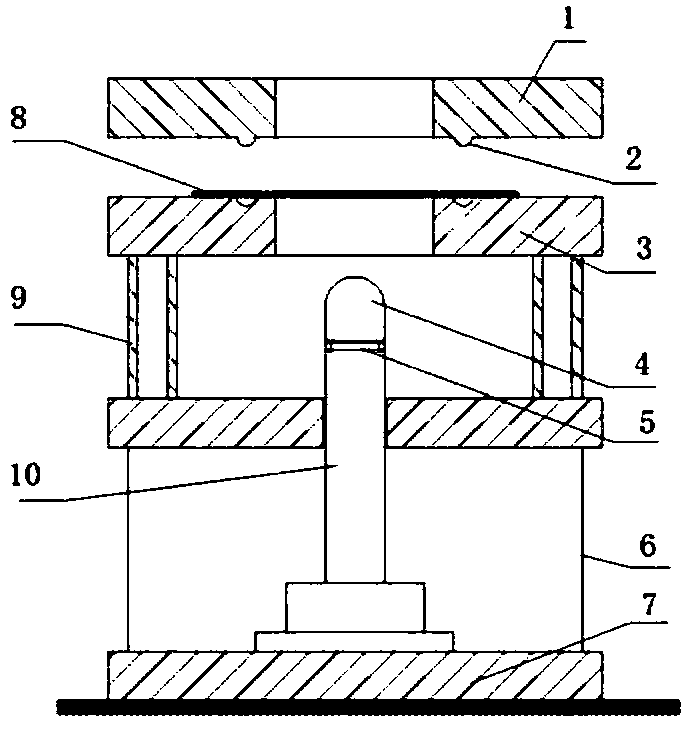
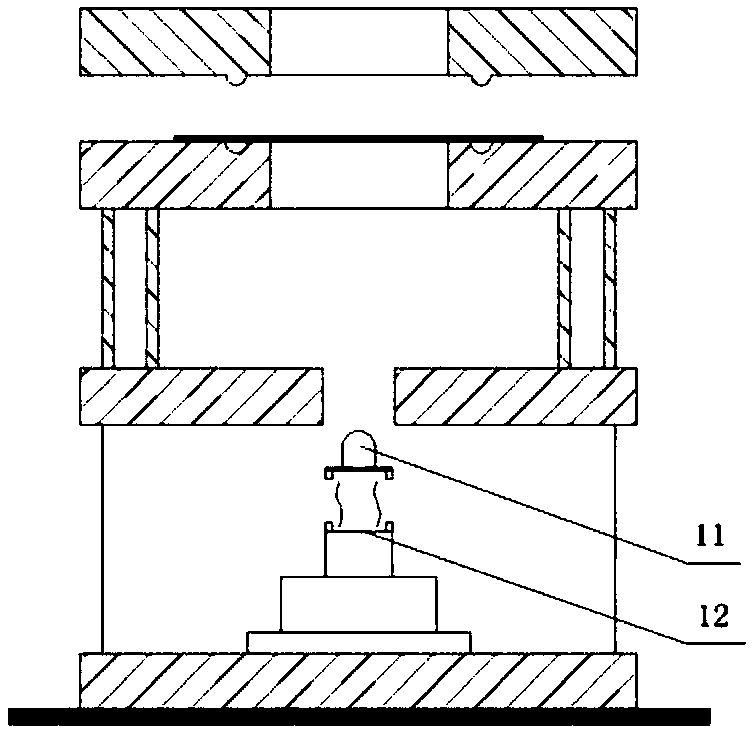
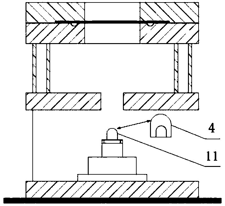
[0029] A test device for obtaining a forming limit diagram under complex loading conditions provided by the present invention includes a multifunctional sheet metal forming machine and a forming die; the multifunctional sheet material forming machine includes a forming machine base 7, a hydraulic ejector rod and a hydraulic control system; The mold includes a die 1 with a bead, a bezel 3 with a bead, a detachable outer plate 6 and a special punch; the special punch includes a small punch 11 and a large punch 4, and the small punch The upper end of 11 is a hemispherical punch, and the lower end of the small punch 11 is provided with a clamp interface 5, and the clamp interface 5 is used for docking with a vertically movable hydraulic ejector rod 10 connected to the punch. The punch 11 is a special mold for pre-deformation of the sheet metal; the inside of the big punch 4 is a cavity that can be socketed with the small punch 11, and the outside of the big punch 4 is a hemispheric...


PUM

PropertyMeasurementUnit
lengthaaaaaaaaaa

Abstract

The invention discloses a test device and method for acquiring forming limit diagrams under the complicated loading condition and belongs to the technical field of forming processing of metal plates. The test device is formed by refitting a specially made male die on the premise that a multifunctional plate forming machine is included originally, and other devices and molds are original equipment; the specially made male die comprises a small male die and a large male die, a hoop interface is arranged at the lower end of the small male die and used for butt joint with a hydraulic ejection rod, and a cavity capable of being in sleeving connection with the small male die is formed in the large male die. By means of the provided test device and method, complicated loading can be further realized, corresponding predeformation on plates is not required before bulging, and the ageing problem and the relatively complicated test process are avoided. The plates in the same size are adopted, plates in various sizes are not required to be processed, batch processing can be performed, the test time is saved, and the test period is shortened.

Description

Technical field: [0001] The invention belongs to the technical field of sheet metal forming and processing, and in particular relates to a test device and method for obtaining a forming limit diagram under complex loading conditions. Background technique: [0002] The forming limit diagram (Forming Limit Diagram, FLD) is the ultimate strain e 1 、e 2 (engineering strain) or ε 1 , ε 2 (True strain) constitutes a strip-shaped area or curve, which divides the entire graphic area into three parts: safe area, rupture area and critical area. FLD can fully reflect the action of sheet metal in one-way and two-way tensile stress The local forming limit below is a quantitative description of the formability of the sheet metal and a judgment curve for the success or failure of the stamping process. It is important in both the actual stamping production of the sheet metal and the numerical simulation analysis of the sheet metal. application. [0003] There are usually two methods fo...

Claims


Application Information

Patent Timeline
Patent Type & Authority Patents(China)
IPC IPC(8): G01N3/28
CPCG01N3/28G01N2203/0282
Inventor 钱健清周玉沈翔邹军
Owner ANHUI UNIVERSITY OF TECHNOLOGY
Learn More