
X-ray photon counting imaging system based on spherical collimating and imaging method of system

A technology for photon counting and imaging systems, applied in the directions of using apertures/collimators, using radiation for material analysis, and using wave/particle radiation for material analysis, etc. It has high requirements and increases the difficulty of X-ray sources, so as to avoid large area X-ray imaging arrays, reduce processing costs, and reduce costs.

Active Publication Date: 2016-11-09
XIDIAN UNIV
View PDF6 Cites 4 Cited by
  • Summary
  • Abstract
  • Description
  • Claims
  • Application Information

AI Technical Summary

Problems solved by technology

[0005] (1) There are difficulties in processing technology in X-ray focusing
In the X-ray band, the refractive index of the material is slightly less than 1, and the X-ray has a penetrating effect and does not reflect on the surface of the object. Only in the case of grazing incidence can the available reflectivity be displayed, but in order to prevent the X-ray from scattering. Causes a decline in imaging quality, and requires very high roughness of the reflective surface. The root mean square roughness is on the order of angstroms or more than a dozen angstroms, and mirror processing is difficult;
[0006] (2) There is a contradiction between wide field of view imaging and large area array detection technology
The field of view of existing space X-ray imaging devices is usually only a few arc minutes, and the lobster-eye X-ray optical system has a wider field of view, but the lobster-eye X-ray optical system usually requires a large-area X-ray array detector, and the current Some Micro Channel Plate detectors (MCP) and proportional counters (Proportional Counter, PC) usually have a strong background noise, which also increases the difficulty of detecting weak X-ray sources in space

Method used


Image

  • X-ray photon counting imaging system based on spherical collimating and imaging method of system
  • X-ray photon counting imaging system based on spherical collimating and imaging method of system
  • X-ray photon counting imaging system based on spherical collimating and imaging method of system

Examples


Embodiment Construction

[0046] The following will clearly and completely describe the technical solutions in the embodiments of the present invention with reference to the accompanying drawings in the embodiments of the present invention. Obviously, the described embodiments are only some, not all, embodiments of the present invention. Based on the embodiments of the present invention, all other embodiments obtained by persons of ordinary skill in the art without making creative efforts belong to the protection scope of the present invention.

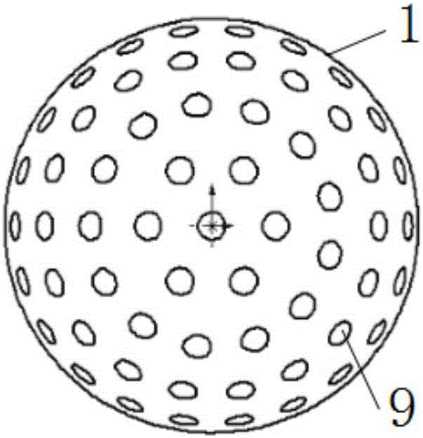
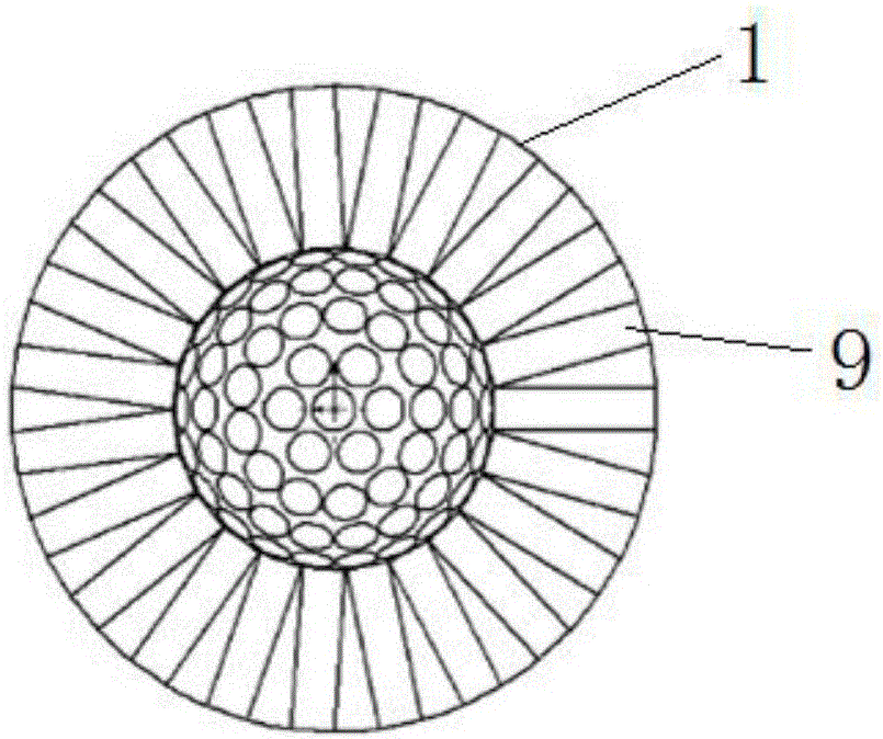
[0047] The X-ray photon counting imaging system based on spherical collimation of the present invention, such as figure 1 As shown in -2, it consists of a spherical X-ray collimator 1, a numerically controlled random shutter array 2, an X-ray single photon counter 3, a high-voltage power supply module 4, an X-ray shielding cavity 5, a photon counting information readout module 6 and an information processing unit 7 Composition: The spherical X-ray collimator 1...


PUM


Abstract

The invention discloses an X-ray photon counting imaging system based on spherical collimating. The system comprises an X-ray single-photon counter, a photon counting information reading module, an information processing unit, a spherical X-ray collimator and a numerical control random shutter array, wherein the X-ray single-photon counter is used for detecting X-ray photons and outputting detected light pulse signals to the photon counting information reading module, the photon counting information reading module is used for recording the counting value of X-ray photons and outputting the counting value to the information processing unit, the information processing unit generates a random observation matrix and controlling the opening and the closing of the numerical control random shutter array, the output end of the information processing unit is connected with the numerical control random shutter array, the spherical X-ray collimator is used for collecting X-rays from space in different directions, the output end of the spherical X-ray collimator is connected with the numerical control random shutter array, the numerical control random shutter array is used for controlling the opening and closing of each channel of the spherical X-ray collimator, and when a shutter is opened, the X-rays in the channel corresponding to the shutter are linearly transmitted to the X-ray single-photon counter. The problems that in the prior art, an X-ray imaging system is small in view field and large in manufacturing process difficulty are solved.

Description

technical field [0001] The invention belongs to the technical field of X-ray astronomical imaging, and relates to an X-ray photon counting imaging system based on spherical collimation and an imaging method thereof. Background technique [0002] There are two main types of existing astronomical X-ray source imaging methods: the first type is transmission imaging, and pinhole imaging is the simplest, oldest, and most practical imaging method when there are no reflection and refraction elements. It was originally applied in the visible light band, and later the pinhole structure has been used in the X-ray band. The smaller the hole, the higher the resolution of the image. However, when performing astronomical observations, the too small aperture limits the average number of X-ray photons. Therefore, it was later developed into multi-pinhole coded aperture imaging, which increases the photon count value per unit time by increasing the number of holes. This imaging system has a ...

Claims


Application Information

Patent Timeline
IPC IPC(8): G01N23/04G01N23/083G21K1/02
CPCG01N23/04G01N23/083G21K1/02
Inventor 孙海峰李小平刘彦明方海燕李铁薛梦凡沈利荣
Owner XIDIAN UNIV
Learn More