A laser radar sensing illumination system and method

A technology of laser radar and lighting system, which is applied in the field of laser radar sensing lighting system, can solve problems such as noise pollution, achieve the effect of eliminating noise pollution and increasing reliability

Inactive Publication Date: 2016-11-09
成都希德电子信息技术有限公司
View PDF3 Cites 8 Cited by
  • Summary
  • Abstract
  • Description
  • Claims
  • Application Information

AI Technical Summary

Problems solved by technology

[0004] The technical problem to be solved by the present invention is that noise pollution is likely to occur when the sound-activated lighting is used at night. The purpose is to provide a laser radar sensing lighting system and method, which can automatically turn on the lighting when the presence of a moving object is detected by the laser radar scanning device. Can eliminate noise pollution caused by voice-activated lighting, convenient and quick

Method used


Image

  • A laser radar sensing illumination system and method
  • A laser radar sensing illumination system and method

Examples


Embodiment 1

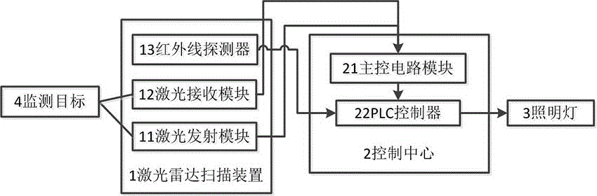
[0025] Such as figure 1 As shown, the laser radar sensing lighting system of the present invention includes a laser radar scanning device 1 , a control center 2 and a lighting lamp 3 .

[0026] The laser radar scanning device 1 includes: a laser emitting module 11, which is used to emit pulsed laser light, and sends a signal reflecting the time of pulsed laser light emission to the main control circuit module 21; a laser receiving module 12, which is used to receive the reflected light from the detected area Pulse laser, and send a signal reflecting the time of receiving the pulse laser to the main control circuit module 21; the infrared detector 13 is used to monitor the existence or movement of the human body in the target area through the pyroelectric element.

[0027] The control center 2 includes: a main control circuit module 21, which is used to receive the time when the laser emitting module 11 emits pulsed laser light and the time when the laser receiving module 12 re...

Embodiment 2

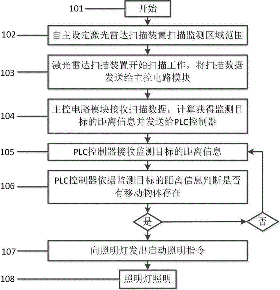
[0030] Such as figure 2 As shown, it is a flowchart of the lidar sensing lighting method:

[0031] Step 101, start;

[0032] Step 102, the manager or the user independently sets the range of the scanning monitoring area of ​​the lidar scanning device;

[0033] Step 103, the laser radar scanning device starts scanning work, and sends the scanning data to the main control circuit module; wherein, the scanning data includes: a signal reflecting the pulse laser emission time and a signal reflecting the time of receiving the pulse laser; the main control circuit module is the present With technology, FPGA can be used to control the circuit board;

[0034] Step 104, the main control circuit module receives the scanning data, calculates and obtains the distance information of the monitoring target and sends it to the PLC controller;

[0035] Step 105, the PLC controller receives the distance information of the monitoring target;

[0036] Step 106, the PLC controller judges wheth...


PUM


Abstract

The invention discloses a laser radar sensing illumination system comprising a laser radar scanning device, a control center and an illuminating lamp. The laser radar scanning device comprises a laser emission module and a laser reception module. The control center comprises a master control circuit module and a PLC controller. The laser radar sensing illumination method comprises the following steps: an optical radar scanning device scans in the monitoring area and sends the scanning data to the master control circuit module; the master control circuit module receives the scanning data, obtains the distance of a monitoring target through calculation, and sends the distance information of the monitoring target to the master control circuit board; the PLC controller receives the monitoring target distance information and judges whether there is a moving object in the monitoring area according to the distance information, and sends a starting instruction to a lighting lamp if the PLC controller detects that there is a moving object in the monitoring area; and the lighting lamp receives the starting instruction of PLC controller and turns on the circuit lighting. Noise pollution due to sound control illuminating lamps can be eliminated, and convenience and rapidness are realized.

Description

technical field [0001] The invention relates to the application of a laser radar scanning device in a lighting system, in particular to a laser radar sensing lighting system and method. Background technique [0002] Lidar is a radar system that emits laser beams to detect characteristic quantities such as the position and speed of targets. In terms of working principle, there is no fundamental difference from microwave radar: a detection signal (laser beam) is emitted to the target, and then the received signal reflected from the target (target echo) is compared with the transmitted signal, and after appropriate processing , the relevant information of the target can be obtained, such as target distance, azimuth, height, speed, attitude, and even shape parameters, so as to detect, track and identify the target. LiDAR is widely used in scanning and monitoring the size of target obstacles and the distance between them and other objects, as well as the running speed of target ...

Claims


Application Information

Patent Timeline
Patent Type & Authority Applications(China)
IPC IPC(8): G01S7/481H05B37/02
CPCG01S7/4817H05B47/105Y02B20/40
Inventor 严强王晓维凃海洋李薪杨永刚
Owner 成都希德电子信息技术有限公司
Why Eureka
Try Eureka