
Sheath injection type water-blocking factice filling equipment and production technology

A technology for water-blocking ointment and filling equipment, which is applied in the directions of light guides, optics, instruments, etc., can solve the problems of increasing equipment maintenance costs, adverse health effects, and large amount of ointment filling, and achieves good water-blocking effect. Stable product quality and low ointment consumption

Active Publication Date: 2016-11-09
HUBEI KAILE SCI & TECH
View PDF4 Cites 7 Cited by
  • Summary
  • Abstract
  • Description
  • Claims
  • Application Information

AI Technical Summary

Problems solved by technology

These two grease filling methods are commonly used in the optical cable industry. The first method must completely fill the gaps in the cable core, and there will inevitably be a thick layer of grease on the outside of the cable core during filling. The amount of filling used is very large, which increases the manufacturing cost; the second filling method saves a lot in cost control compared with the first filling method because it only sprays a layer of ointment on the steel and aluminum strip. However, a large amount of oil mist will be generated during the spraying production process, and the oil mist will have a great impact on environmental sanitation if the oil mist is scattered in the air; Maintenance costs, and after the electrical components of the equipment are damaged, unqualified products such as broken belts or cables will be produced during production, which will increase the manufacturing cost; third, the long-term inhalation of oil mist by the operator during the production process will have adverse effects on health

Method used


Image

  • Sheath injection type water-blocking factice filling equipment and production technology

Examples


Embodiment Construction

[0018] The present invention will be further described below in conjunction with the drawings as follows:

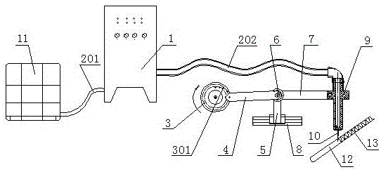
[0019] The sheathed injection type water-blocking ointment filling equipment is composed of an electrical control cabinet 1, an ointment barrel 11, an injection device and an operation control device. One side of the electrical control cabinet 1 is connected to the ointment barrel 11 through an ointment delivery pipe a201, and the electrical The other side of the control cabinet 1 is connected to the injection device through the ointment delivery pipe b202; one side of the injection device is equipped with an operation control device. The injection device is composed of an oil gun 9, an oil injection needle 10, and a fixed connecting arm 7. A through hole is made in the center of the oil gun 9, and the lower end of the through hole is equipped with an oil injection needle 10 through a fixing member; A shoulder is made on the upper part, and a fixed connecting arm 7 is fixed...


PUM


Abstract

The invention relates to a sheath injection type water-blocking factice filling equipment and production technology, and belongs to the technical field of communication optical cable product production. The sheath injection type water-blocking factice filling equipment comprises an electrical control cabinet, a factice barrel, an injection device and an operation controller, wherein one side of the electrical control cabinet is connected with the factice barrel through a factice conveyer pipe a, the other side of the electrical control cabinet is connected with the injection device through a factice conveyer pipe b, and the operation controller is installed on one side of the injection device. After factice in the factice barrel is conveyed to an oil gun and an injection oil needle, the injection oil needle swings above a steel aluminum band and injects the factice on the steel aluminum band in an S shape, and the factice after entering into a lateral wrapping die wraps an optical cable core with the steel aluminum band in a circular shape. The water-blocking factice filling amount is great for current whole-process filling, and the manufacture cost is high. The factice spraying pollutes environment and may damage electric components, which may cause unqualified products such as breaking strands or cables. The manufacture cost is further increased.

Description

Technical field [0001] The invention relates to a sheath injection type water-blocking ointment filling equipment and production process, and belongs to the technical field of communication optical cable product production. Background technique [0002] Communication optical cables are required to have good water blocking performance to ensure stable signal transmission performance of optical fibers during long-term use. At present, there are generally two ways of filling water-blocking ointment in sheathing. One is to fill the water-blocking ointment with the cable core through the pressure ointment barrel, so that the water-blocking ointment fills all gaps in the cable core. ; The second is to use spraying equipment to spray a layer of water-blocking grease on the steel-aluminum strip, and then to wrap the steel-aluminum strip longitudinally with the cable core through the longitudinal wrapping mold. These two ointment filling methods are commonly used in the optical cable ind...

Claims


Application Information

Patent Timeline
Patent Type & Authority Applications(China)
IPC IPC(8): G02B6/44
CPCG02B6/44384
Inventor 刘世平马继鸿成赵念刘经贵李明颜复兵邝永华王纪肖
Owner HUBEI KAILE SCI & TECH
Learn More