

Display device with solar cell
A technology for solar cells and display devices, which is applied to identification devices, circuits, capacitors, etc., can solve the problems of low solar energy conversion efficiency and unstable incident angle, so as to improve the photoelectric conversion efficiency, increase the photocurrent density, and improve the conversion efficiency. Effect
- Summary
- Abstract
- Description
- Claims
- Application Information
AI Technical Summary
Problems solved by technology
Method used
Image

Examples
Embodiment 1
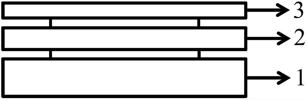
[0043] Depend on figure 1 , an embodiment of the present application relates to a display device with a solar cell, comprising:
[0044] A backlight module 1, which provides a backlight source for the display device;
[0045] a solar cell 2, arranged above the backlight module 1 to receive the backlight;
[0046] The display panel 3 is arranged above the solar cell 2 to receive the backlight penetrating the solar cell.
[0047] Preferably, the backlight module 1 , the solar cell 2 and the display panel 3 are connected, and the solar cell 2 provides electric energy for the display panel 3 .
[0048] Preferably, the backlight module 1 includes a light shield, a light source, a diffusion sheet and a prism sheet.
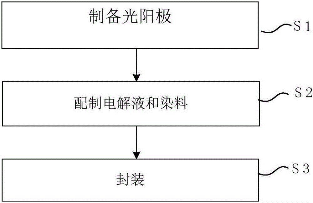
[0049] Preferably, said solar cell 2 is based on a dye-sensitized solar cell.
[0050] Preferably, the dye-sensitized solar cell consists of a photoanode, a counter electrode, and an electrolyte; structure and dye molecules; the transition layer is a Cr film transi...
Embodiment 2
[0066] Depend on figure 1 , an embodiment of the present application relates to a display device with a solar cell, comprising:
[0067] A backlight module 1, which provides a backlight source for the display device;
[0068] a solar cell 2, arranged above the backlight module 1 to receive the backlight;
[0069] The display panel 3 is arranged above the solar cell 2 to receive the backlight penetrating the solar cell.
[0070] Preferably, the backlight module 1 , the solar cell 2 and the display panel 3 are connected, and the solar cell 2 provides electric energy for the display panel 3 .
[0071] Preferably, the backlight module 1 includes a light shield, a light source, a diffusion sheet and a prism sheet.
[0072] Preferably, said solar cell 2 is based on a dye-sensitized solar cell.
[0073] Preferably, the dye-sensitized solar cell consists of a photoanode, a counter electrode, and an electrolyte; structure and dye molecules; the transition layer is a Cr film transi...
Embodiment 3
[0089] Depend on figure 1 , an embodiment of the present application relates to a display device with a solar cell, comprising:
[0090] A backlight module 1, which provides a backlight source for the display device;
[0091] a solar cell 2, arranged above the backlight module 1 to receive the backlight;
[0092] The display panel 3 is arranged above the solar cell 2 to receive the backlight penetrating the solar cell.
[0093] Preferably, the backlight module 1 , the solar cell 2 and the display panel 3 are connected, and the solar cell 2 provides electric energy for the display panel 3 .
[0094] Preferably, the backlight module 1 includes a light shield, a light source, a diffusion sheet and a prism sheet.
[0095] Preferably, said solar cell 2 is based on a dye-sensitized solar cell.
[0096] Preferably, the dye-sensitized solar cell consists of a photoanode, a counter electrode, and an electrolyte; structure and dye molecules; the transition layer is a Cr film transi...
PUM
 Abstract
Description
Claims
Application Information