
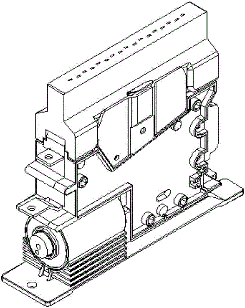
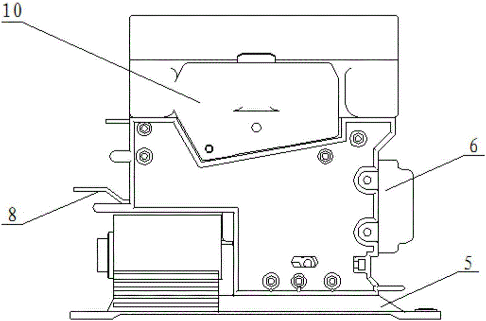
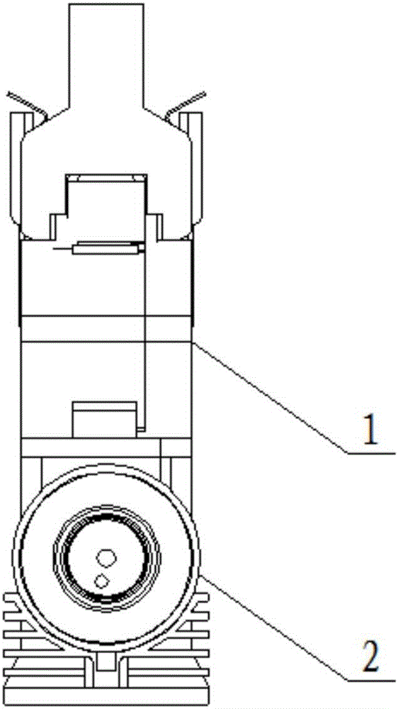
High voltage direct current contactor with magnetic coil arc quenching

A high-voltage DC, contactor technology, applied in electromagnetic relays, electromagnetic relay details, relays, etc., can solve problems such as high operating voltage requirements, burning of main contacts, inability to pull off, etc., to enhance the induction magnetic field, safety The effect of reliable contact and long service life

Inactive Publication Date: 2016-11-09
GUIZHOU TIANYI ELECTRICAL
View PDF6 Cites 8 Cited by
  • Summary
  • Abstract
  • Description
  • Claims
  • Application Information

AI Technical Summary

Problems solved by technology

When the product is used on high-speed rail transit vehicles, the working voltage is required to be high, and the load current is also large. When the power is turned on and off, a strong arc will be generated, which will cause the contacts to weld and form a bond. , cannot disconnect
[0007] In order to solve the problem that the traditional contactor cannot be broken due to the arc generated when the high-voltage load is turned on and off, resulting in the burning or bonding of the main contact, in order to improve the service life of the high-voltage DC contactor, it is necessary to improve the arc extinguishing technology Research

Method used


Image

  • High voltage direct current contactor with magnetic coil arc quenching
  • High voltage direct current contactor with magnetic coil arc quenching
  • High voltage direct current contactor with magnetic coil arc quenching

Examples


Embodiment 1

[0056] Suppose the rated working current is 250A, and its working voltage is 1500V~2000V.

[0057] Such as Figure 7 As shown, the realization principle of this technical solution:

[0058] Current flow direction of the product: the positive pole of the power supply is connected to the moving contact 8; the moving contact 8 is connected to the moving contact 2 9 and the arc reed B12; the static contact 1509 is connected to the load.

[0059] When the active contact A11 and the static contact three 1511 are in conduction and are connected stably, the current flows from the moving contact one 8 to the moving contact two 9, through the active contact A11 and the static contact three 1511, and the static contact one 1509 Through, forming a current loop with the load.

[0060] At the moment when the auxiliary moving contact A902 and the static contact piece 1512 are turned on and off, the contact between the moving contact A902 and the static contact piece 1512 generates an arc due to hig...

Embodiment 2

[0066] In addition, the contact material no longer uses AgCu, AgNi and other materials, but adopts the addition of trace rare metal elements in the AgSnO2 alloy. This material has high thermal stability, welding resistance and low material transfer characteristics. SnO2 particles In silver melting, the viscosity of molten metal can be increased and arc erosion can be reduced. After repeated arc action, the SnO2 component can still be retained on the contact surface, and the arc erosion resistance and fusion welding resistance of the contact will not be significantly reduced, so it has a high service life, so AgSnO2 has excellent arc erosion resistance and wear resistance Damage and improve the ablation resistance of the product.

Embodiment 3

[0068] When the 110V power supply voltage is applied to the coil of the electromagnet assembly 2, the electromagnet assembly 2 starts to move under the action of the magnetic force, driving the push rod 18 to move, and the pushing rod 18 pushes the reed 14, which is attached to the micro switch 6, so that The micro switch 6 is turned on to realize the control signal output.

[0069] At the same time, the push rod 18 drives one end of the pendulum rod 13 to swing around its hinge point to a certain extent, and the movable contact piece 9 rotates counterclockwise accordingly. The auxiliary moving contact A902 first contacts the static contact piece 1502. At the moment of contact, the current flows through Movable connecting piece 8, moving connecting piece 9, auxiliary moving contact A902, static connecting piece 1512, adjusting screw 1501, magnetic ring coil 1506, embedded nut B1504, static connecting piece 1 1509 to the load, forming an instantaneous loop, An arc is generated bet...


PUM


Abstract

The invention discloses a high voltage direct current contactor with magnetic coil arc quenching, and belongs to the contactor technical field. The high voltage direct current contactor with the magnetic coil arc quenching comprises a shell and a base, wherein the shell is fixedly connected with the base. A magnetic ring coil assembly and a swinging rod are arranged in the shell. A moving contact pin 2 is fixed on the top of the swinging rod. An electromagnet assembly is arranged under the shell. A movable end of the electromagnet assembly is connected to one end of the swinging rod through a pushing rod. The pushing rod can push the swinging rod to rotate around an installation shaft. The technical scheme adopts magnetic ring winding coils to generate an induced magnetic field so as to provide a magnetic blow-out arc quenching system. The induced magnetic field generated in the winding coils correspondingly changes along with the high- low of an instantaneous voltage level, so that the magnetic blow-out force is different. The magnetic field is guided in a vertical direction of a current flowing direction of a contact through a baffle, and an electric arc is more effectively blown to a cavity of a specified arc quenching room for segment arc quenching. The damage of the contact in a product is prevented.

Description

Technical field [0001] The invention belongs to the technical field of contactors, and relates to a vehicle DC contactor used for rail transit locomotives and electric vehicles, in particular to a high-voltage DC contactor with a magnetic coil for arc extinguishing. Background technique [0002] The high-voltage DC contactor is a kind of switching element that works in the power system. When the power system needs to be turned on and off, the contactor can be turned on or off by controlling the coil control terminal with a lower voltage level to achieve To achieve the purpose of connecting or disconnecting high-voltage lines. Most of the existing domestic high-voltage DC contactors adopt the traditional non-sealed structure, use a single main contact to connect or disconnect, and use magnetic steel as a permanent magnet, placed on both sides of the static contact piece, and determine the magnetic field according to the current flow. The N pole and S pole direction of the steel u...

Claims


Application Information

Patent Timeline
Patent Type & Authority Applications(China)
IPC IPC(8): H01H50/38
CPCH01H50/38
Inventor 辜飞
Owner GUIZHOU TIANYI ELECTRICAL
Learn More