Ultra wide-band filter response power divider

A technology of power divider and filter response, which is applied in the direction of waveguide devices, electrical components, connection devices, etc., and can solve the problems of low skirt steepness, inability to extend further, slow drop rate of filter response passband edge, etc.

Active Publication Date: 2016-11-09
XIDIAN UNIV
View PDF3 Cites 5 Cited by
  • Summary
  • Abstract
  • Description
  • Claims
  • Application Information

AI Technical Summary

Problems solved by technology

[0004] In March 2008, Zhewang Ma, Wenqing He and others published "A Novel Compact Ultra-Wideband BandpassFilter Using Microstrip Stub-Loaded Dual -Mode Resonator Doublets”, proposed an ultra-wideband filter, which can realize ultra-wideband of 3.3-10.4GHz, and the ultra-wideband operating bandwidth only covers 3.3-10.4GHz, and cannot perform power division
[0005] In January 2010, Kaijun Song and others published "Novel Ultra-Wideband (UWB) Multilayer Slotline Power Divider With Bandpass Response", a power divider with ultra-wideband filtering characteristics is proposed. Although this method can perform power division, the frequency band coverage can only reach 3.1GHz to 11.5GHz, which just covers the frequency range defined by ultra-wideband and cannot be further extended. , in order to achieve a wider frequency range, so that it cannot be used in the Ku band of satellite communication, and at the same time, the filtering response is slower at the edge of the passband, and the skirt is less steep

Method used


Image

  • Ultra wide-band filter response power divider
  • Ultra wide-band filter response power divider
  • Ultra wide-band filter response power divider

Examples


Embodiment Construction

[0020] Embodiments of the present invention are described in detail below in conjunction with accompanying drawings:

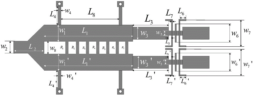
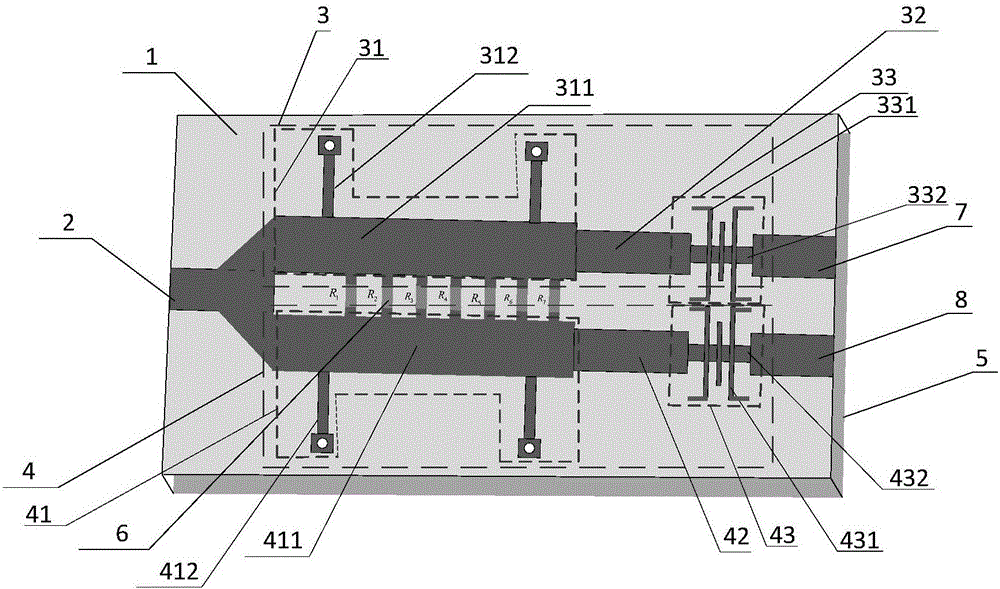
[0021] refer to figure 1 , figure 2 and image 3 , the present invention mainly consists of a microstrip dielectric substrate 1, an input port 2, two output ports 7,8, two upper and lower broadband filters 3,4, two upper and lower high-pass filter units 31,41, and two upper and lower stepped impedance transmission lines 32 , 42, two upper and lower low-pass filter units 33, 43, a metal ground plate 5, and an isolation resistor 6, wherein:

[0022] The microstrip dielectric substrate 1 adopts a double-sided copper-clad dielectric substrate with a dielectric constant of 2.45 and a plate thickness of 1mm, and a metal ground plate 5 under the double-sided copper-clad laminate;

[0023] The upper and lower high-pass filter units 31, 41 have the same structure and are placed symmetrically, that is, the upper high-pass filter unit 31 has a length of L 1 , with a...


PUM


Abstract

The invention discloses an ultra wide-band filter response power divider, and mainly solves the problem that the band width of a power divider is too narrow in the prior art. The ultra wide-band filter response power divider comprises a micro-strip dielectric substrate (1), an input port (2), two output ports (7, 8), an upper wide-band filter (3) and a lower wide-band filter (4), wherein the upper wide-band filter (3) is formed by cascading a high-pass filtering unit (31), a step impedance transmission line (32) and a low-pass filtering unit (33). The high-pass filtering unit consists of a main transmission line and a pair of short circuit branch knots, the low-pass filtering unit is formed by cascading three low impedance transmission lines and four pairs of high impedance branch knots alternately, and the high-pass filtering unit and the low-pass filtering unit are connected through the step impedance transmission line in a matching manner; the lower wide-band filter (4) and the upper wide-band filter (3) are the same in structures and are symmetrically arranged, and an isolating resistor (6) is arranged between the lower wide-band filter (4) and the upper wide-band filter (3). The ultra wide-band filter response power divider can realize band-pass filtering response of 3GHz to 16GHz, and can be used for the radio frequency front ends of wireless communication systems.

Description

technical field [0001] The invention belongs to the technical field of microwave devices, in particular to an ultra-wideband filter response power divider, which can be used for a radio frequency front end of a wireless communication system. Background technique [0002] With the rapid development of communication technology, people have higher and higher requirements for information transmission systems, hoping to obtain more spectrum resources to increase data transmission rates, improve system security, and reduce production costs. In this context, ultra-wideband UWB technology has become a research hotspot in the field of wireless communication because of its simple system structure, low cost, low power consumption, high security, low interference, and high data transmission rate. In the wireless communication system, the power splitter and the filter are two important microwave devices, which are often used together in the RF front-end circuit of the communication syste...

Claims


Application Information

Patent Timeline
Patent Type & Authority Applications(China)
IPC IPC(8): H01P5/16
CPCH01P5/16
Inventor 吴边刘津林徐扬夏磊李龙
Owner XIDIAN UNIV
Why Eureka
Try Eureka