a receiving antenna

A technology for receiving antenna and antenna, which is applied in the direction of antenna, antenna grounding switch structure connection, radiation unit cover, etc., can solve the problems of affecting the verticality of the inner conductor, increasing the processing difficulty, aggravating the deformation problem, etc., and achieving the processing and assembly efficiency and cost. The effect of improving, avoiding the problem of machining error and avoiding the problem of assembly error

Active Publication Date: 2018-09-04
ANHUI SUN CREATE ELECTRONICS
View PDF4 Cites 0 Cited by
  • Summary
  • Abstract
  • Description
  • Claims
  • Application Information

AI Technical Summary

Problems solved by technology

The defect of the above structure is that: due to the joint-by-joint welding structure between the above-mentioned inner conductors, the welding deformation of the inner conductors often occurs due to the welding internal stress and the difference in welding technology, and the welding deformation of the inner conductors often occurs with the accumulation of the welding number of the inner conductors. Aggravate its deformation problem, which greatly affects the verticality of the inner conductor
Especially for some slender inner conductors, due to the extremely high processing requirements for their verticality, the processing difficulty increases, which in turn has an adverse effect on the actual use cost and processing cycle of the inner conductor
Since the inner conductor exists as the mounting base and positioning mandrel of the outer conductor, once there is a problem with the verticality of the inner conductor, the assembly accuracy of the entire receiving antenna will be impossible to talk about
In addition, the screw connection method between the inner conductor and the outer conductor often has assembly accuracy problems due to the existence of assembly errors, which will have a negative impact on the antenna telecommunications parameters

Method used


Image

  • a receiving antenna
  • a receiving antenna
  • a receiving antenna

Examples


Embodiment Construction

[0038] For ease of understanding, combined here Figure 1-9 Concrete structure of the present invention and course of work are described further as follows:

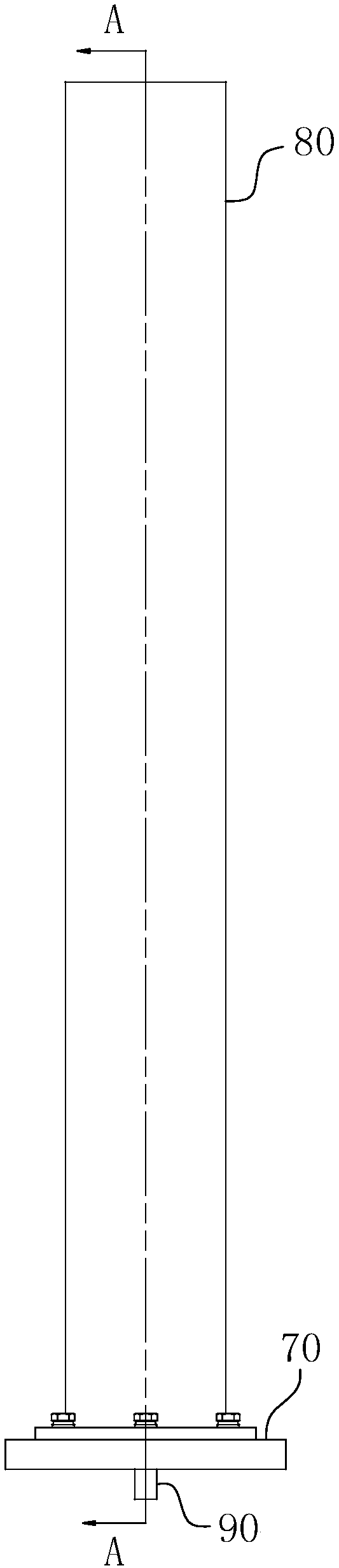
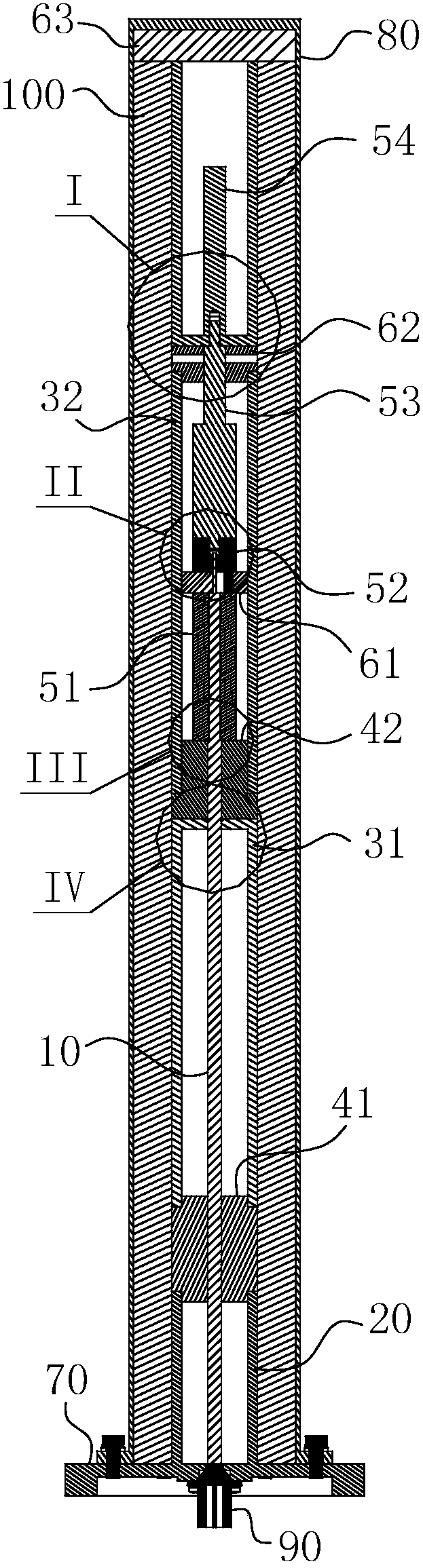
[0039] The concrete structure of the present invention is as Figure 1-2 and Figure 7-8 As shown, it includes an antenna module, a foam support 100 and a radome 80 from inside to outside. Wherein, the opening of the radome 80 is fixedly connected to the installation base 70 , so that the cavity enclosed by the two constitutes an accommodating cavity for accommodating the antenna module and the foam support 100 . The foam support 100 serves to fill the fit gap between the antenna module and the radome 80 to ensure the structural stability of the antenna module after assembly.

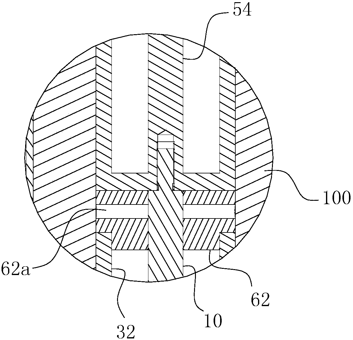
[0040] As far as the antenna module is concerned, the details are as follows: Figure 1-6 When the structure is shown, it includes a radio frequency coaxial semi-rigid cable 10 with an N-type connector, a reflector 20, two outer conductors, tw...


PUM


Abstract

The invention belongs to the field of radar electronic communication and specifically relates to a receiving antenna. The antenna comprises a radio frequency coaxial semi-rigid cable, a reflection plate, a first outer conductor insulating support, a first outer conductor, a second outer conductor insulating support and a second outer conductor. The antenna further comprises a first inner conductor, a second inner conductor, a third inner conductor and a fourth inner conductor which are coaxially arranged with the radio frequency coaxial semi-rigid cable. The radio frequency coaxial semi-rigid cable, the inner conductors, the outer conductors and the insulating supports form an antenna module together. The antenna module is installed on an installation base. An antenna cover covers the antenna module, and the cover opening of the antenna cover and the installation base form a flange fixed matching. The radial fit clearance between the antenna cover and the antenna module is filled by foam supports. The receiving antenna solves the problem that the inner conductors of a long and thin structure are difficult to machine, and the machining and assembling precision of the inner conductors and the outer conductors are effectively ensured.

Description

technical field [0001] The invention belongs to the field of radar electronic communication, and in particular relates to a receiving antenna. Background technique [0002] In the field of radar electronics, the receiving antenna is an important component of the radar transmission signal, and the accuracy of the processing and assembly of the receiving antenna determines the accuracy of the radar's exploration target. The current receiving antenna structure generally includes a protective cover and an inner conductor and an outer conductor located in the cavity of the cover. When in use, the shaft ends between the inner conductors are welded section by section, with the screw connection structure between the inner conductor and the outer conductor, and then the outer protective cover is used to finally form the specific style of the receiving antenna. The defect of the above structure is that: due to the joint-by-joint welding structure between the above-mentioned inner con...

Claims


Application Information

Patent Timeline
Patent Type & Authority Patents(China)
IPC IPC(8): H01Q1/42H01Q1/50H01Q19/10
CPCH01Q1/42H01Q1/50H01Q19/10
Inventor 王家明刘鲁军高静丁飞姜炎陈晶晶
Owner ANHUI SUN CREATE ELECTRONICS
Why Eureka
Try Eureka