
An improved adaptive droop control method for parallel inverters in low-voltage microgrids

A control method and inverter technology, applied in the microgrid field, can solve the inherent contradictions of load sharing and output voltage quality, which are difficult to compromise, and achieve the effect of solving the problem of voltage drop

Active Publication Date: 2018-08-10
安徽博衡电力科技有限公司
View PDF2 Cites 0 Cited by
  • Summary
  • Abstract
  • Description
  • Claims
  • Application Information

AI Technical Summary

Problems solved by technology

[0004] Sun Xiaofeng, Yang Yalin, Zhao Wei, Shen Hong, Tan Guangjun. In 2014, they published the paper "Adaptive Droop Control Strategy for Micro-Grid Inverters" in "Grid Technology" and proposed an adaptive droop control strategy. The inherent contradiction of output voltage quality is difficult to compromise

Method used


Image

  • An improved adaptive droop control method for parallel inverters in low-voltage microgrids
  • An improved adaptive droop control method for parallel inverters in low-voltage microgrids
  • An improved adaptive droop control method for parallel inverters in low-voltage microgrids

Examples


Embodiment 1

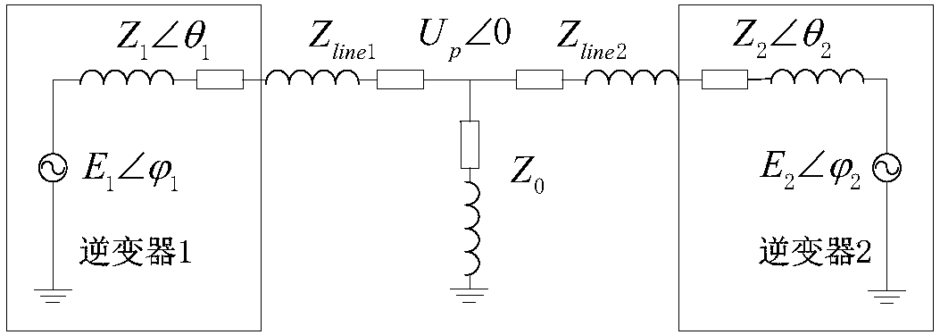
[0060] Using Simulink as the simulation platform, two three-phase inverters are connected to the same section of AC bus, and the equivalent mathematical model is shown in the figure. figure 1 shown. The main parameters of the main circuit of the parallel inverter are: the input DC voltage is 700V, the output voltage is 220V / 50Hz, the rated active power of a single inverter is 1.7KW, the rated reactive power is 500Var, the filter inductance is 3.14mL, and the filter capacitor is 100uF, and the corner frequency of the power filter is 20rad / s. Take a set of sag coefficients m as 0.00004 and n as 0.0012. The simulation waveform is as follows Figure 7 As shown in (7a) and (7b), after the two parallel inverters are running stably, the common load is suddenly increased to 2.6KW when t is 0.06s. It can be seen that the improved droop control algorithm introduces dynamic adjustment coefficients. , the current waveform changes very gently. When the output current of the two inverter...

Embodiment 2

[0062] Two 1.7KW three-phase two-level inverters are connected in parallel as the experimental platform. The control system uses the TMS320FM2812 control chip, the switching frequency is set to 12.8KHz, and the resistive line impedance of 1Ω is added in the experiment to simulate the impedance on the traditional low-voltage power line. The experimental parameters are consistent with the simulation. The average load current waveform of the parallel inverter in stable operation can be obtained, and the dynamic experimental waveform of the parallel inverter current when the load suddenly increases at the moment of 0.06s. Experimental waveforms such as Figure 8 It shows that the improved droop control algorithm adopted can better realize the load power sharing when two inverters are connected in parallel, and the dynamic performance of the output current is better when the load changes suddenly. The effectiveness of the improved control algorithm is verified.


PUM


Abstract

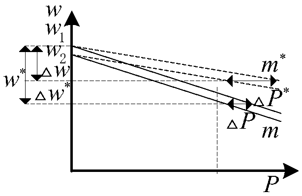
The invention relates to an improved adaptive droop control method for parallel inverters in a low-voltage microgrid. The method includes the following steps that: virtual complex impedance is introduced, so that the equivalent output impedance of the parallel inverters can be inductive, and a droop control equation can be obtained; linear function terms of power and droop coefficients are introduced to replace droop coefficients in the droop control equation, so that an adaptive droop control equation can be obtained; and voltage drop caused by the extraction of the virtual complex impedance is considered, so that an improved adaptive droop control equation is obtained. Improved adaptive droop control on the parallel inverters is realized through the improved adaptive droop control method. Compared with the prior art, the improved adaptive droop control method of the invention has the advantages of quick dynamic response and high stability, and can realize a compromise between the load sharing and output voltage quality of the parallel inverters.

Description

technical field [0001] The invention relates to the field of microgrids, in particular to an improved adaptive droop control method for parallel inverters in low-voltage microgrids. Background technique [0002] With the development of distributed energy, the distribution network side has higher requirements for power supply quality, power supply reliability, and system capacity. The parallel connection of multiple inverters can increase the power of the system. After forming a microgrid, it can provide users with high-quality electric energy and increase the reliability of the power supply of the system. Inverter paralleling technology is divided into two control methods with connecting lines and those without connecting lines. There is a tie line method, mainly through the information of each parallel module in the detection system, and the upper computer issues instructions to complete the parallel connection. Its main disadvantage is that the communication line is pron...

Claims


Application Information

Patent Timeline
Patent Type & Authority Patents(China)
IPC IPC(8): H02J3/38
CPCH02J3/38
Inventor 陈坤曹以龙赵乐孔亚非
Owner 安徽博衡电力科技有限公司
Learn More