Ultrasonic fluid imaging method and ultrasonic fluid imaging system

An imaging method and fluid technology, applied in ultrasonic/sonic/infrasonic diagnosis, structure of ultrasonic/sonic/infrasonic diagnostic equipment, radio wave measurement system, etc. Image information, etc.

Active Publication Date: 2016-11-09
SHENZHEN MINDRAY BIO MEDICAL ELECTRONICS CO LTD
View PDF4 Cites 21 Cited by
  • Summary
  • Abstract
  • Description
  • Claims
  • Application Information

AI Technical Summary

Problems solved by technology

Two-dimensional ultrasound scanning can only reflect the size and direction of blood flow velocity on the scanning plane
The display technology based on two-dimensional ultrasound images cannot truly reproduce the flow of fluid in any tubular or fluid-storage organs such as blood vessels. The display technology based on two-dimensional images is often isolated in several sections, or through several sections However, the reproduced pseudo-3D images cannot provide doctors with more, more comprehensive and accurate detection image information.

Method used


Image

  • Ultrasonic fluid imaging method and ultrasonic fluid imaging system
  • Ultrasonic fluid imaging method and ultrasonic fluid imaging system
  • Ultrasonic fluid imaging method and ultrasonic fluid imaging system

Examples


Embodiment Construction

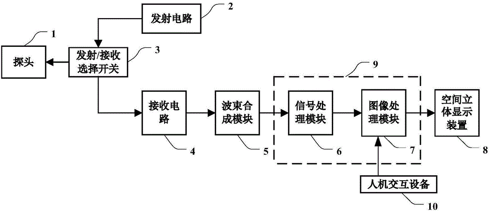
[0044] figure 1 It is a schematic structural block diagram of an ultrasound imaging system according to an embodiment of the present invention. Such as figure 1 As shown, the ultrasound imaging system generally includes: a probe 1 , a transmitting circuit 2 , a transmitting / receiving selection switch 3 , a receiving circuit 4 , a beamforming module 5 , a signal processing module 6 , an image processing module 7 and a spatial stereoscopic display device 8 .

[0045] During the ultrasonic imaging process, the transmitting circuit 2 transmits the delayed-focused transmitting pulse with a certain amplitude and polarity to the probe 1 through the transmitting / receiving selection switch 3 . The probe 1 is excited by the transmitted pulse, and transmits ultrasonic waves to the scanning target (for example, organs, tissues, blood vessels, etc. in the human body or animal, not shown in the figure), and receives the ultrasonic waves reflected from the target area after a certain delay....


PUM


Abstract

An ultrasonic fluid imaging method and an ultrasonic imaging system. The system comprises: a probe (1); a transmission circuit (2) for exciting the probe to transmit body ultrasonic beams to a scanned target; a receiving circuit (4) and a beamforming module (5) for receiving an echo of the body ultrasonic beams to obtain a body ultrasonic echo signal; a data processing module (9) for obtaining, according to the body ultrasonic echo signal, fluid velocity vector information and three-dimensional ultrasonic image data of a target point inside the scanned target; and a spatial three-dimensional display apparatus (8) for displaying the three-dimensional ultrasonic image data to form a spatial three-dimensional image of the scanning target, and superposing the fluid velocity vector information on the spatial three-dimensional image. The system provides a better multi-angular observation view for a user by means of a 3D display technique.

Description

technical field [0001] The invention relates to fluid information imaging and display technology in an ultrasonic system, in particular to an ultrasonic fluid imaging method and an ultrasonic imaging system. Background technique [0002] In medical ultrasound imaging equipment, common fluid display technologies are only based on the display of two-dimensional images. Taking blood flow imaging as an example, ultrasonic radiation is radiated into the object to be inspected. Like pulse wave and continuous wave Doppler, color Doppler blood flowmeter also uses the Doppler effect between red blood cells and ultrasonic waves to realize imaging. . Color Doppler flowmeter includes two-dimensional ultrasound imaging system, pulse Doppler (one-dimensional Doppler) blood flow analysis system, continuous wave Doppler blood flow measurement system and color Doppler (two-dimensional Doppler) ) blood flow imaging system. The oscillator generates two orthogonal signals with a phase differ...

Claims


Application Information

Patent Timeline
Patent Type & Authority Applications(China)
IPC IPC(8): A61B8/06A61B8/00
CPCA61B8/06A61B8/44A61B8/46A61B8/466A61B8/483A61B8/5215G01S15/8984G01S15/8993G01S7/52068G01S7/52071G01S7/52073G01S15/8925G01S15/8927A61B5/745G03H3/00G03H2001/0088G03H2210/42A61B8/085A61B8/0891A61B8/4466A61B8/462A61B8/463A61B8/488A61B8/5207A61B8/5223A61B8/5246G16H50/30
Inventor 杜宜纲樊睿
Owner SHENZHEN MINDRAY BIO MEDICAL ELECTRONICS CO LTD
Why Eureka
Try Eureka