
Efficient rust-removing device for iron rod for hardware machining

An iron rod and high-efficiency technology, which is applied in the field of high-efficiency iron rod derusting devices for hardware processing, can solve the problems of large size, high price and long time consumption of derusting machines, and achieve the effect of high cost performance, small size and simple operation

Active Publication Date: 2016-11-16
TANGSHAN JINSHI SUPER ABRASIVE
View PDF6 Cites 47 Cited by
  • Summary
  • Abstract
  • Description
  • Claims
  • Application Information

AI Technical Summary

Problems solved by technology

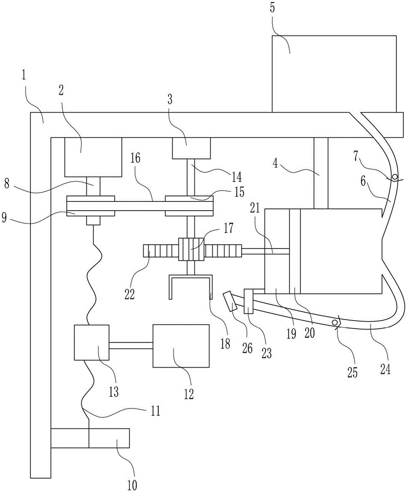
[0005] In order to overcome the existing physical derusting of iron and steel mainly relying on manual manpower, long time consumption and low efficiency, the operator has been in contact with rust for a long time, which has an impact on the health of the operator, while mechanical derusting requires professionalism. The rust machine has the shortcomings of large size and high price. The technical problem to be solved by the present invention is to provide a small size, high cost performance, simple operation, no requirement for professionalism, no manpower, convenient, efficient, safe and reliable, and the operating environment is more comfortable for the operator. High-efficiency derusting device for iron rods for metal processing with less health hazards

Method used


Image

  • Efficient rust-removing device for iron rod for hardware machining
  • Efficient rust-removing device for iron rod for hardware machining
  • Efficient rust-removing device for iron rod for hardware machining

Examples


Embodiment 1

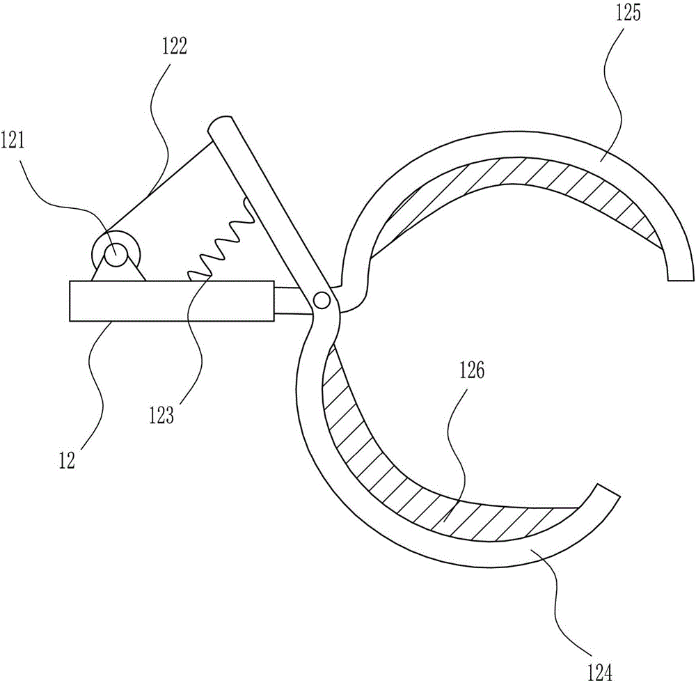
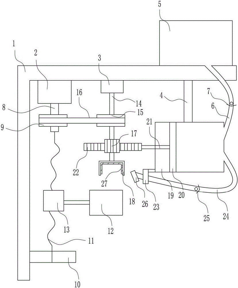
[0028] A high-efficiency derusting device for iron rods for metal processing, such as Figure 1-4As shown, it includes an L-shaped bracket 1, a motor 2, a first bearing seat 3, a pole 4, a water tank 5, a water inlet pipe 6, a first one-way valve 7, a first rotating shaft 8, a first pulley 9, and a second bearing Seat 10, screw mandrel 11, clamping device 12, nut 13, second rotating shaft 14, second pulley 15, flat belt 16, gear 17, thumb cylinder 18, compression cylinder 19, piston 20, push rod 21, rack 22 , guide sleeve 23, water outlet pipe 24, second one-way valve 25, nozzle 26, the inner top of L-shaped bracket 1 is provided with motor 2, first bearing seat 3 and pole 4 in turn from left to right, L-shaped bracket 1 A water tank 5 is arranged on the right side of the top of the water tank 5, and a water inlet pipe 6 is connected to the bottom of the water tank 5. The water inlet pipe 6 is provided with a first one-way valve 7, and the output shaft of the motor 2 is connec...


PUM


Abstract

The invention relates to an iron rod rust removing device, in particular to an efficient rust-removing device for an iron rod for hardware machining. In order to solve technical problems in the prior art, the efficient rust-removing device being small in size, high in cost performance, free of professional requirements and manpower, convenient, rapid, efficient, safe and reliable, and having the advantage that the damage of the operating environment to the health of operating personnel is relatively small is provided. The efficient rust-removing device comprises an L-shaped bracket, a motor, a first bearing seat, a supporting rod, a water tank, a first one-way valve, a first rotating shaft, a first belt wheel, a second bearing seat, a lead screw, a clamping device and the like, wherein the motor and several other components are arranged at the inner top of the L-shaped bracket from left to right. Friction blocks perform reciprocating motion up and down and matched with the rotating iron rod for rust removing, so that the efficient rust-removing device provided by the invention achieves the effects of being small in size, high in cost performance, simple to operate, free of professional requirements and manpower, convenient, rapid and efficient.

Description

technical field [0001] The invention relates to an iron rod derusting device, in particular to an iron rod derusting device with high efficiency for metal processing. Background technique [0002] Hardware: traditional hardware products, also known as "hardware". Refers to the five metals of gold, silver, copper, iron, and tin. After manual processing, it can be made into works of art or metal devices such as knives and swords. Hardware in modern society is more extensive, such as hardware tools, hardware parts, daily hardware, construction hardware and security supplies. Most hardware products are not final consumer goods. [0003] Due to improper protection of steel and steel exposed to the air for a long time, it is easy to rust the steel and cause the quality of the steel to decline. At present, the metal processing industry mainly chooses physical rust removal for steel rust removal. The existing physical rust removal for steel mainly relies on manual manpower, whic...

Claims


Application Information

Patent Timeline
IPC IPC(8): B24B27/033B24B55/02B24B41/06B24B41/00B24B5/36B08B3/02F26B21/00
CPCB08B3/02B24B5/363B24B27/033B24B41/005B24B41/067B24B55/02F26B21/004
Inventor 朱连成
Owner TANGSHAN JINSHI SUPER ABRASIVE
Learn More