Aircraft and flight system

An aircraft and governor technology, applied in the field of aircraft, can solve the problems of reducing the experience of aircraft, high ground environment requirements, reducing the effect of advancing and accelerating, and achieving good advancing and accelerating effects, reducing ground environment requirements, conversion Stable and smooth process

Inactive Publication Date: 2016-11-16
YUNEEC TECH CO LTD
View PDF8 Cites 4 Cited by
  • Summary
  • Abstract
  • Description
  • Claims
  • Application Information

AI Technical Summary

Problems solved by technology

[0002] At present, due to the characteristics of small size, light weight, flexible operation and high safety, the aircraft has been widely used in aerial photography, surveillance, search and rescue, reconnaissance and other technical fields. Realize the advancement and acceleration of the aircraft. This method makes the aircraft have higher requirements on the ground environment during take-off and landing, requires a larger space and a relatively flat area, and requires operators to have a higher level of operation. Oscillation damage to the main body of the aircraft, reducing the safety of user operations
The aircraft that directly changes the fixed wing to the rotor, although it reduces the requirements for the ground environment, greatly reduces the effect of its advancement and acceleration, and reduces the user experience of using the aircraft.
[0003] In view of the fact that the aircraft in the above-mentioned traditional technology has high requirements on the ground environment during take-off and landing, and it is easy to cause vibration damage to the main body of the aircraft during landing, which reduces the safety of the user's operation, thereby reducing the user's experience in using the aircraft. effective solution

Method used


Image

  • Aircraft and flight system
  • Aircraft and flight system
  • Aircraft and flight system

Examples


Embodiment 1

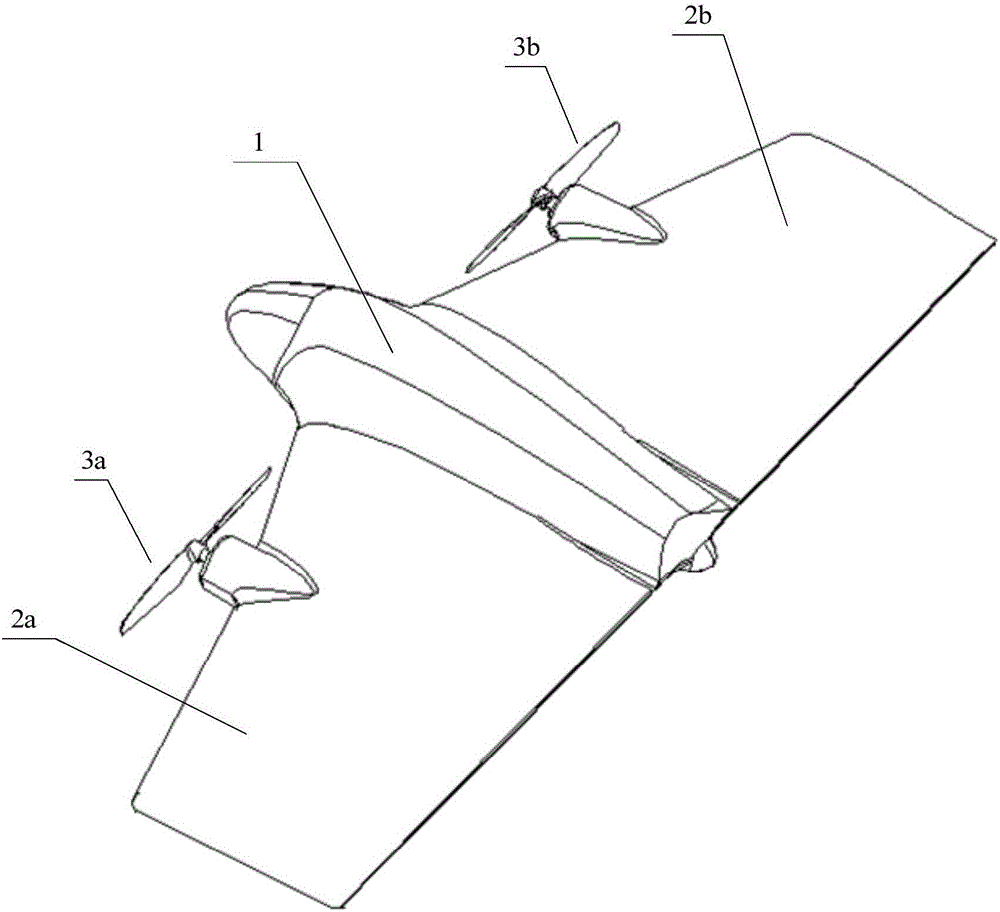
[0038] see figure 1 Shown is a schematic diagram of the three-dimensional structure of the rotor of an aircraft, the aircraft includes: a fuselage body 1 and wings 2a and 2b on both sides of the fuselage body 1, symmetrically arranged on the wings 2a and 2b on both sides of the aircraft Rotor 3a and 3b, rotor 3a and 3b are equipped with the motor that provides power respectively ( figure 1 Not shown in ) and the governor connected to the motor ( figure 1 Not shown in ), the governor and the main control board of the aircraft ( figure 1 not shown in ) electrical connection; the main control board controls the rotating speed of the motor through the governor, and drives the rotors 3a and 3b to rotate to control the vertical takeoff, landing and hovering of the aircraft.

[0039] The plane of rotation of the rotor 3a and 3b is perpendicular to the plane where the wings 2a and 2b are, and the rotor 3a and 3b pass through the rotor holder ( figure 1 not shown in ) are respective...

Embodiment 2

[0052] In order to facilitate the further understanding of the aircraft provided by the embodiment of the present invention, on the basis of Embodiment 1, the present invention also provides a block diagram of the circuit control principle of the aircraft described in Embodiment 1 above, as Figure 9 As shown, specifically, the block diagram of the circuit control principle of the aircraft mainly includes the following components: main control board, air pressure sensor, GPS sensor, nine-axis sensor, governor, steering gear, wireless transmission module and sensor components, wherein, Figure 9 Only one governor and steering gear are shown, and they can be flexibly set according to the structure of a specific aircraft during actual implementation, which is not limited in this embodiment.

[0053] Wherein, the air pressure sensor, the GPS sensor and the nine-axis sensor are electrically connected with the main control board. The air pressure sensor is used to detect the air pre...

Embodiment 3

[0059] On the basis of Embodiment 1 and Embodiment 2, an embodiment of the present invention further provides a flight system, the flight system includes the aircraft in the above embodiments, and a controller of the aircraft, wherein the aircraft communicates with the controller wirelessly.

[0060] The controller of the above-mentioned aircraft includes: a remote control of the aircraft, or a mobile terminal, such as: a mobile phone, a tablet computer, a PDA (Personal Digital Assistant, a handheld computer), a laptop portable computer, a vehicle-mounted computer, and the like.

[0061] The aircraft and the controller establish communication through the wireless transmission module installed on the main control board. The aircraft sends the real-time parameters received by the main control board to the controller through the wireless transmission module. The real-time parameters include: the current flight altitude of the aircraft, positioning information and driving parameter...


PUM


Abstract

The invention provides an aircraft and a flight system. The aircraft comprises a fuselage body and wings on the two sides of the fuselage body. Rotors are symmetrically arranged on the wings on the two sides of the aircraft. The rotors are provided with motors for supplying power and speed adjusters connected with the motors. The speed adjusters are electrically connected with a main control panel of the aircraft. The rotary plane of the rotors is perpendicular to the plane where the wings are located. By the adoption of the aircraft and the flight system, the rotors symmetrically arranged on the wings on the two sides of the aircraft rotate in the plane perpendicular to the plane where the wings are located so that the aircraft can achieve vertical takeoff and landing in a rotor mode, the requirements for the environment of the ground in the takeoff and landing processes of the aircraft are lowered, an aircraft body is effectively prevented from being oscillated and damaged by the ground when the aircraft lands, and the user operation safety and the experience degree of the aircraft used by a user are improved.

Description

technical field [0001] The present invention relates to the technical field of aircraft, in particular, to an aircraft and a flight system. Background technique [0002] At present, due to the characteristics of small size, light weight, flexible operation and high safety, the aircraft has been widely used in aerial photography, surveillance, search and rescue, reconnaissance and other technical fields. Realize the advancement and acceleration of the aircraft. This method makes the aircraft have higher requirements on the ground environment during take-off and landing, requires a larger space and a relatively flat area, and requires operators to have a higher level of operation. The main body of the aircraft caused vibration damage, reducing the safety of the user's operation. The aircraft that directly changes the fixed wing to the rotor, although it reduces the requirements for the ground environment, greatly reduces the effect of its advancement and acceleration, and red...

Claims


Application Information

Patent Timeline
Patent Type & Authority Applications(China)
IPC IPC(8): B64C3/00B64C27/08B64C29/00
CPCB64C3/00B64C27/08B64C29/00
Inventor 田瑜江文彦
Owner YUNEEC TECH CO LTD
Why Eureka
Try Eureka