Combined connecting end and preparation method thereof
A connecting end and combined technology, applied in the field of the combined connecting end and its preparation, can solve the problems of difficult forging of the connecting end, high forging difficulty, low strength, etc., so as to overcome the excessive forging difficulty and improve the strength. , the effect of prolonging the service life
- Summary
- Abstract
- Description
- Claims
- Application Information
AI Technical Summary
Problems solved by technology
Method used
Image
Examples
Embodiment 1
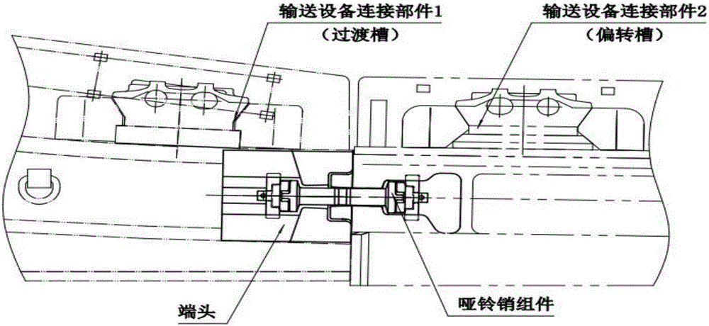
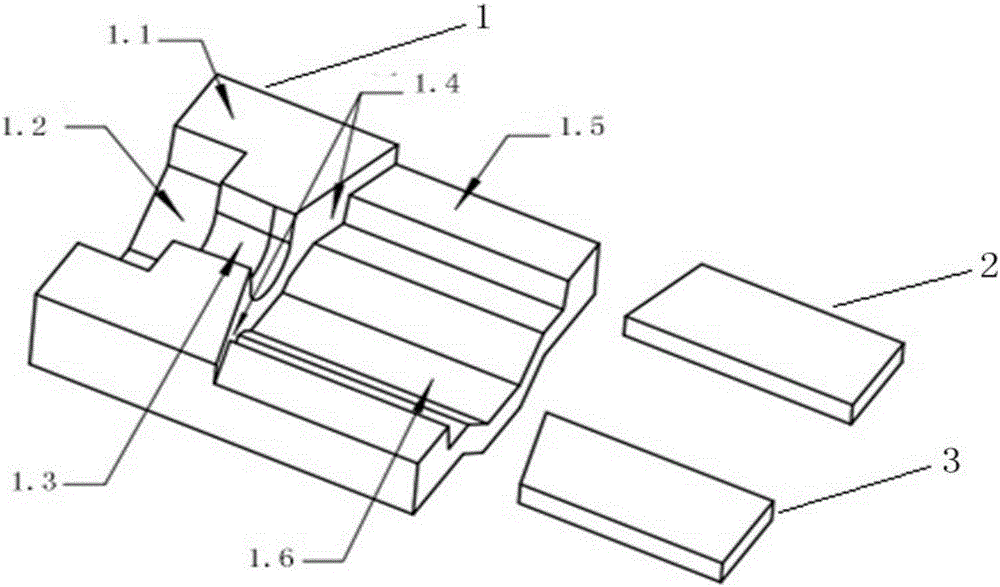
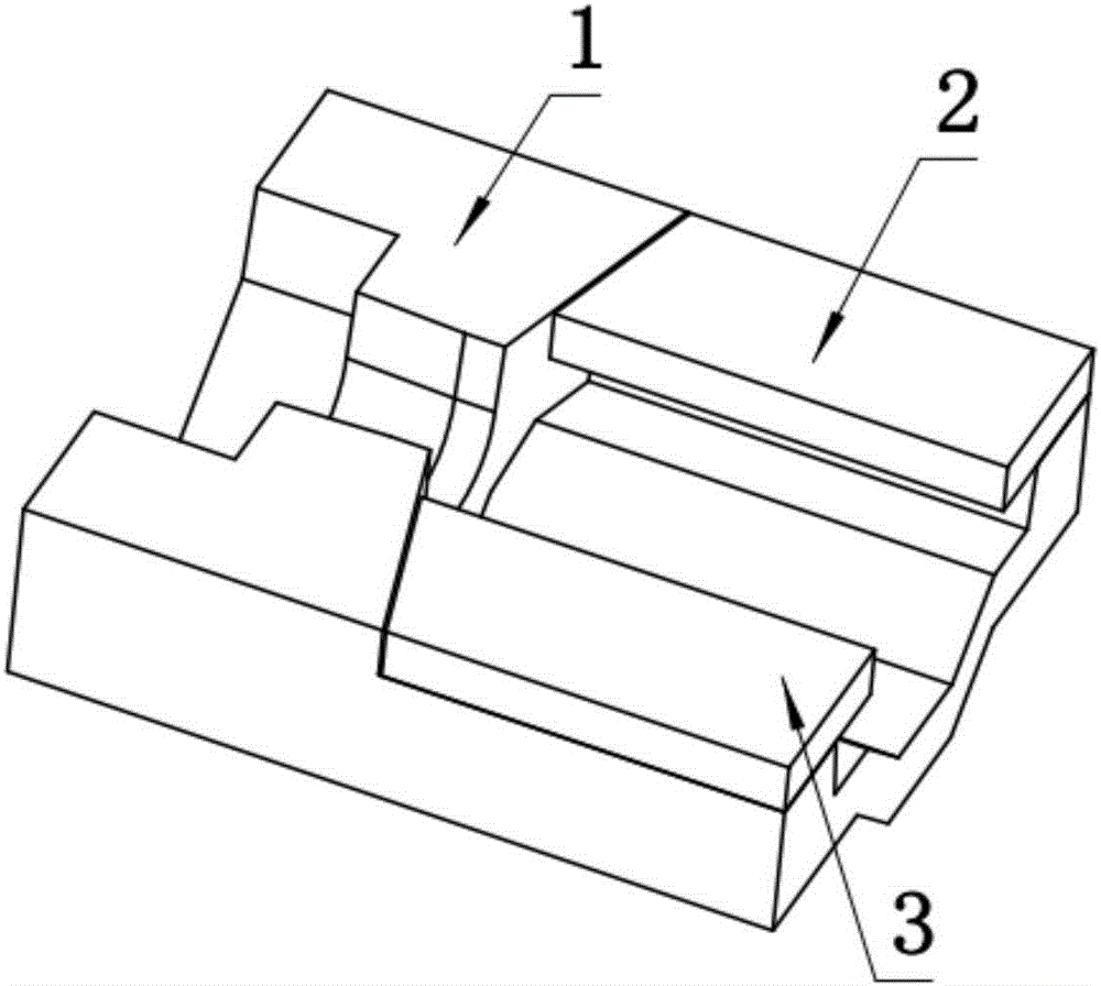
[0027] Example 1, such as figure 1 , figure 2 , image 3 A combined connection terminal, including a base 1, a cover plate 2 and a cover plate 3, the upper surface of the base 1 is connected by a left convex plane 1.1 and a right concave plane 1.5 to form a stepped surface; the base convex The middle part of the starting plane 1.1 is provided with a first U-shaped groove 1.2, which is used to place the middle part of the dumbbell pin of the connector, and has a certain gap with the middle part of the dumbbell pin, so that a certain amount of activity can be connected between the grooves to ensure The middle groove is bent horizontally and vertically at a certain angle. The dumbbell pin connection is a kind of flexible connection, which can adapt to a certain degree of uneven ground or push and pull bending, can withstand high tensile, bending and shearing forces, etc., and is easy to disassemble. There is also an inline groove 1.3 in the middle of the raised plane 1.1 of t...
Embodiment 2
[0028] Example 2, such as figure 1 , figure 2 , Figure 4A combined connection terminal, including a base 1, a cover plate 2 and a cover plate 3, the upper surface of the base 1 is connected by a left convex plane 1.1 and a right concave plane 1.5 to form a stepped surface; the base convex The middle part of the starting plane 1.1 is provided with a first U-shaped groove 1.2, which is used to place the middle part of the dumbbell pin of the connector, and has a certain gap with the middle part of the dumbbell pin, so that a certain amount of activity can be connected between the grooves to ensure The middle groove is bent horizontally and vertically at a certain angle. The dumbbell pin connection is a kind of flexible connection, which can adapt to a certain degree of uneven ground or push and pull bending, can withstand high tensile, bending and shearing forces, etc., and is easy to disassemble. There is also an inline groove 1.3 in the middle of the raised plane 1.1 of t...
Embodiment 3
[0029] Example 3, such as figure 1 , figure 2 , Figure 4 A combined connection terminal, including a base 1, a cover plate 2 and a cover plate 3, the upper surface of the base 1 is connected by a left convex plane 1.1 and a right concave plane 1.5 to form a stepped surface; the base convex The middle part of the starting plane 1.1 is provided with a first U-shaped groove 1.2, which is used to place the middle part of the dumbbell pin of the connector, and has a certain gap with the middle part of the dumbbell pin, so that a certain amount of activity can be connected between the grooves to ensure The middle groove is bent horizontally and vertically at a certain angle. The dumbbell pin connection is a kind of flexible connection, which can adapt to a certain degree of uneven ground or push and pull bending, can withstand high tensile, bending and shearing forces, etc., and is easy to disassemble. There is also an inline groove 1.3 in the middle of the raised plane 1.1 of ...
PUM
 Abstract
Description
Claims
Application Information
 - R&D
- Intellectual Property
- Life Sciences
- Materials
- Tech Scout
- Unparalleled Data Quality
- Higher Quality Content
- 60% Fewer Hallucinations
Browse by: Latest US Patents, China's latest patents, Technical Efficacy Thesaurus, Application Domain, Technology Topic, Popular Technical Reports.
© 2025 PatSnap. All rights reserved.Legal|Privacy policy|Modern Slavery Act Transparency Statement|Sitemap|About US| Contact US: help@patsnap.com


