
Propellant powder filling machine

A filling machine and propellant technology, which is applied in pyrotechnics, offensive equipment, weapon types, etc., can solve problems such as physical health impact, flammable and explosive dangerous drugs, and impact on product quality, so as to ensure the personal safety of workers and prevent personal threats Safe and does not affect the effect of product quality

Active Publication Date: 2016-11-16
HUNAN CHINASUN PHARMA MASCH CO LTD
View PDF8 Cites 9 Cited by
  • Summary
  • Abstract
  • Description
  • Claims
  • Application Information

AI Technical Summary

Problems solved by technology

[0002] In the process of fireworks production, due to the technical requirements, it is necessary to fill the propellant into the inner tube of the fireworks. The propellant is a granular item similar to the size of millet. In the past, the filling of the drug was done manually, and the labor intensity of the workers was high. The production efficiency Low, it is easy to cause waste of raw materials and affect product quality
Later, semi-automatic filling devices appeared, but these devices still require manual operation of the filling blocking board, and the blocking board is pulled once for each filling. Repeated work requires a lot of physical strength, and workers are exposed to drugs for a long time, which is harmful to their health. There is a great impact, exposure to flammable and explosive dangerous drugs at work, threatening personal safety

Method used


Image

  • Propellant powder filling machine
  • Propellant powder filling machine
  • Propellant powder filling machine

Examples


Embodiment Construction

[0019] The present invention will be further described below in conjunction with the accompanying drawings and embodiments.

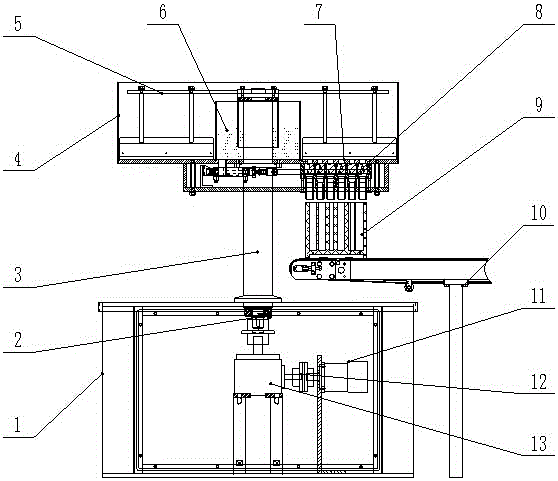
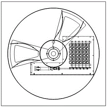
[0020] Referring to the accompanying drawings, this embodiment includes a frame 1, a rotating mechanism, a filling mechanism and a conveying mechanism 10; 13. The column 3 is installed on the frame 1, the rotating shaft 2 is installed on the column 3, the lower end of the rotating shaft 2 is connected with the reducer 13, and the reducer 13 is connected with the hydraulic motor 11 through the coupling 12 , the feeding plate 5 is installed on the upper end of the rotating shaft 2; the filling mechanism includes a hopper 4, a metering plate 7, a gate opening mechanism 8, a receiving hopper 8-5, a lower hopper 8-6 and a fireworks outer cylinder 9. The hopper 4 is installed on the upper end of the column 3, and a water tank 6 is arranged between the hopper 4 and the column 3, the metering plate 7 is installed in the hopper 4, and is positioned above the hop...


PUM


Abstract

Provided is a propellant powder filling machine. The propellant powder filling machine comprises a machine frame, a rotating mechanism, a filling mechanism and a conveying mechanism. The rotating mechanism comprises a rotary shaft, a stand column, a pushing plate, a hydraulic motor, a coupling and a speed reducer. The stand column is installed on the machine frame. The rotary shaft is installed on the stand column. The lower end of the rotary shaft is connected with the speed reducer. The speed reducer is connected with the hydraulic motor through the coupling. The pushing plate is installed at the upper end of the rotary shaft. The filling mechanism comprises a hopper, a metering plate, a gate opening mechanism, a collection hopper, a discharging hopper and an outer firework drum, wherein the hopper is installed at the upper end of the stand column; a water trough is arranged between the hopper and the stand column; the metering plate is installed in the hopper and located above the collection hopper; the gate opening mechanism and the collection hopper are installed below the hopper; the gate opening mechanism is connected with the hopper; the collection hopper is connected with the discharging hopper; and the outer firework drum is located above the conveying mechanism. When powder is charged through the propellant powder filling machine, the advantages that the labor intensity of workers is low, the production efficiency is high, raw material waste is not likely to be caused, the product quality is not influenced, and physical safety of the workers is guaranteed are achieved.

Description

technical field [0001] The invention relates to a propellant filling machine. Background technique [0002] In the process of fireworks production, due to the technical requirements, it is necessary to fill the propellant into the inner tube of the fireworks. The propellant is a granular item similar to the size of millet. In the past, the filling of the drug was done manually, and the labor intensity of the workers was high. The production efficiency Low, it is easy to cause waste of raw materials and affect product quality. Later, semi-automatic filling devices appeared, but these devices still require manual operation of the filling blocking board, and the blocking board is pulled once for each filling. Repeated work requires a lot of physical strength, and workers are exposed to drugs for a long time, which is harmful to their health. There is a great impact, contact with flammable and explosive dangerous drugs at work, threatening personal safety. Contents of the inv...

Claims


Application Information

Patent Timeline
Patent Type & Authority Applications(China)
IPC IPC(8): F42B4/30
CPCF42B4/30
Inventor 张旭罗斌
Owner HUNAN CHINASUN PHARMA MASCH CO LTD
Learn More