Laser vibration measurement calibration big trigger delay accumulation calibration method

A technology of trigger delay and laser vibration measurement, which is applied in measuring devices, using wave/particle radiation, measuring ultrasonic/sonic/infrasonic waves, etc. It can solve the problems that the delay of the delayer cannot be set arbitrarily, and the accuracy is not easy to be high.

Active Publication Date: 2016-11-16
BEIJING CHANGCHENG INST OF METROLOGY & MEASUREMENT AVIATION IND CORP OF CHINA
View PDF7 Cites 9 Cited by
  • Summary
  • Abstract
  • Description
  • Claims
  • Application Information

AI Technical Summary

Problems solved by technology

[0009] The purpose of the present invention is to overcome the shortcomings of the existing trigger delay calibration method. The measurement calibration for the large delay trigger of the digital oscilloscope requires a high-precision large delay device, and the delay of the delay device can not be set arbitrarily, and the accuracy is not easy to be very high. Based on the technical status quo of laser vibrometer calibration, a cumulative calibration method with large trigger delay is proposed

Method used


Image

  • Laser vibration measurement calibration big trigger delay accumulation calibration method
  • Laser vibration measurement calibration big trigger delay accumulation calibration method
  • Laser vibration measurement calibration big trigger delay accumulation calibration method

Examples


Embodiment 1

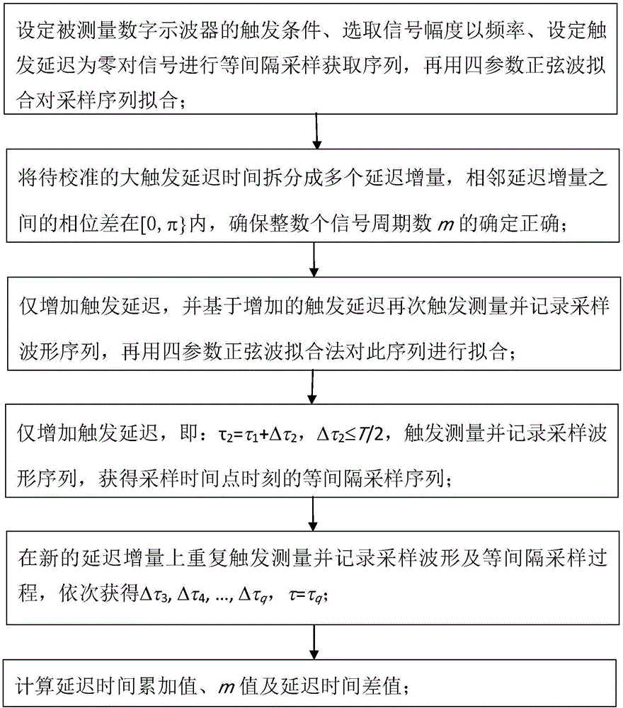
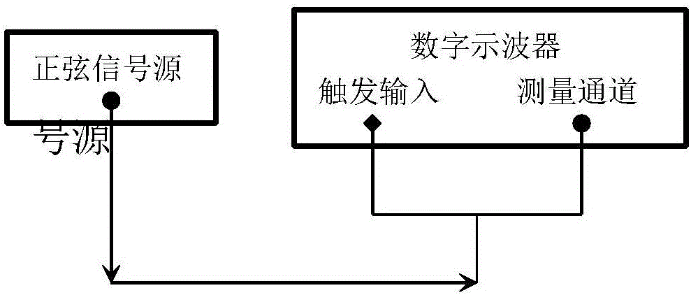
[0095] This embodiment describes the implementation process of the method proposed in the present invention, a laser vibrometer calibration with a large trigger delay cumulative calibration method, which is specifically realized by measuring the large trigger delay with a digital oscilloscope. The flow chart is as follows figure 1 As shown, the schematic diagram of the principle is shown in figure 2 shown.

[0096] From figure 1 It can be seen that the implementation process of the cumulative calibration method with a large trigger delay in the proposed method of the present invention is a kind of laser vibration measurement calibration, including:

[0097] Step 1: Set the trigger condition of the digital oscilloscope to be measured, select the signal amplitude and frequency, set the trigger delay to zero, sample the signal at equal intervals to obtain the sequence, and then use the four-parameter sine wave fitting to fit the sampling sequence;

[0098] Step 2: Split the la...

Embodiment 2

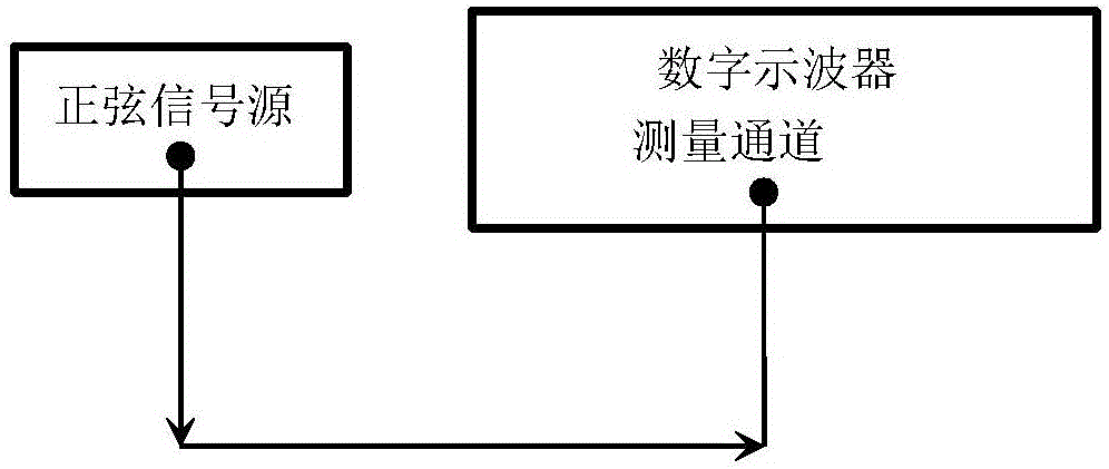
[0119] This embodiment illustrates another implementation process of the method proposed in the present invention, an accumulation calibration method with a large trigger delay for laser vibrometer calibration, that is, it does not need to be stimulated by a signal source, but is directly triggered by a measurement channel. Its schematic diagram is as follows image 3 shown.

[0120] image 3 In the above, the sinusoidal signal source applies sinusoidal excitation to the digital oscilloscope under test, and at the same time provides it with a sinusoidal trigger signal. The specific process is the same as that of Embodiment 1, except that the trigger channel is the input channel itself, and there is no need to introduce it from a special trigger terminal.

[0121] It can be seen from the above embodiments 1 and 2 that the method of the present invention does not need to use a fixed delayer or a delay circuit, and can perform metering and calibration for trigger delay time dif...

Embodiment 3

[0123] This embodiment illustrates a simplified implementation process of a laser vibrometer calibration with a large trigger delay cumulative calibration method proposed in the present invention, that is: only based on the measurements under the two conditions of maximum trigger delay and zero delay, Determine trigger delay results.

[0124] During the specific implementation of this embodiment, when it is ensured that the maximum allowable error limit of the large trigger delay τ of the digital oscilloscope is not greater than T / 2, when the sine wave with a period of T is used for the maximum delay calibration traceability, the rounding operation m=int[τ can be directly used / T] Confirm and judge the number m of sine wave cycles contained in it, and use the time difference corresponding to the phase difference between the two sine sample sequences when the delay time is 0 and the delay time is τ under the same measurement conditions to calculate less than one wave cycle Part...


PUM


Abstract

The invention provides a laser vibration measurement calibration big trigger delay accumulation calibration method, belonging to the radio metering test technical field, and is characterized in that by utilizing the periodic characteristics measured by a sine waveform phase difference with a period T, i.e., a corresponding time difference increases T when a phase difference increases 2Pi, T measurement accuracy is much higher than the measurement accuracy of the phase difference; the big delay time of a digital oscilloscope is divided into a plurality of small delays, and each small delay is smaller than T so as to guarantee that the number N (N is an integer) of sinusoidal signal period included in measuring and determining big delay time does not occur counting determination errors, and furthermore, a phase difference measuring method is used for measuring time delay less than a T portion, and the time delay is combined into the big delay time difference of the digital oscilloscope; the delay of a laser vibrometer can be read through the big trigger time delay measuring function of the digital oscilloscope. The laser vibration measurement calibration big trigger delay accumulation calibration method can perform measuring calibration on any trigger delay time, and does not have the problems such as insufficient hardware delay measuring range scope, definition, and calibrated points.

Description

technical field [0001] The invention relates to an accumulative calibration method with a large trigger delay for laser vibration measurement calibration, and belongs to the technical fields of radio measurement and test technology, time-frequency radio calibration and measurement. Background technique [0002] For the vibration measurement problem in vibration measurement and calibration, since the signal waveform comes from the sine wave of the electrical signal source, the final output is the sinusoidal vibration waveform output by the vibration table. After passing through electromechanical links such as power amplifiers and mechanical vibration tables, the sinusoidal vibration waveform has a relatively large time delay compared with the sinusoidal waveform in the electrical signal source. If the time delay is greater than one sinusoidal waveform period, it is generally considered to be a large delay. , can not be solved by the direct phase measurement method, and can on...

Claims


Application Information

Patent Timeline
Patent Type & Authority Applications(China)
IPC IPC(8): G01H9/00
CPCG01H9/00
Inventor 梁志国朱振宇
Owner BEIJING CHANGCHENG INST OF METROLOGY & MEASUREMENT AVIATION IND CORP OF CHINA
Why Eureka
Try Eureka