Photoelectrochemical pond and auxiliary device thereof

An auxiliary device, a photoelectrochemical technology, which is used in measurement devices, chemiluminescence/bioluminescence, material analysis by optical means, etc. , does not have the ability to resolve wavelengths, etc., to achieve the effect of improving the ability of analysis and detection

Inactive Publication Date: 2016-11-16
SOUTHEAST UNIV
View PDF1 Cites 1 Cited by
  • Summary
  • Abstract
  • Description
  • Claims
  • Application Information

AI Technical Summary

Problems solved by technology

Although the electrochemiluminescence behavior has been observed in these systems, it is difficult to detect the electrochemiluminescence wavelength of the sample because the current electrochemiluminescence detector does not have the ability of wavelength resolution, which is not conducive to the optical behavior of electrochemiluminescence materials. research and its application
[0003] The current fluorescence spectroscopy technology is very mature, but the fluorescence spectroscopy technology alone can no longer meet everyone's needs. Combining the fluorescence spectroscopy technology with other technologies can not only achieve technological breakthroughs, but also expand the research field of fluorescence spectroscopy technology, greatly Increased utility of fluorescence spectroscopy

Method used


Image

  • Photoelectrochemical pond and auxiliary device thereof
  • Photoelectrochemical pond and auxiliary device thereof

Examples


Embodiment 1

[0020] The creation of embodiment 1 photoelectrochemical cell and its auxiliary equipment

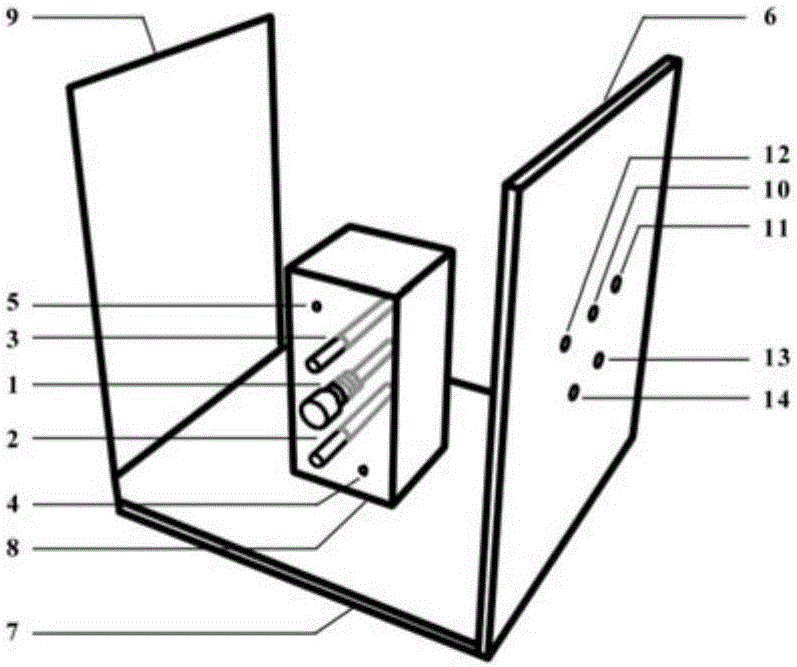
[0021] A photoelectrochemical cell and its auxiliary device. The photoelectrochemical cell and its auxiliary device include two parts: a photoelectrochemical reaction cell and an auxiliary device: the outside of the photoelectrochemical reaction cell includes a peristaltic pump outlet 5 and a counter electrode from top to bottom. interface 3, working electrode interface 1, reference electrode interface 2, and peristaltic pump interface 4; the sample chamber is a semi-enclosed space formed by a front baffle 6, a base 7 and a rear baffle 9, and the base 7 A notch 8 is set, the electrochemical reaction cell is placed on the notch 8 in the sample chamber, and five interfaces are arbitrarily set on the front baffle 6, respectively: working electrode connection port 10, reference electrode connection port 11, Counter electrode wiring port 12, peristaltic pump tube inlet 13, peristaltic pump t...

Embodiment 2

[0022] Embodiment 2 photoelectrochemical cell and auxiliary device thereof

[0023] It includes the combination device composed of the electrochemical workstation of Example 1 and the fluorescence spectrometer. The interface of the working electrode is a screw port, and the position of the interface is aligned with the detector of the fluorescence spectrometer to obtain the combined device.

Embodiment 3

[0024] Embodiment 3 photoelectrochemical cell and auxiliary device thereof

[0025] It is basically the same as that of Example 2, except that the length of the electrochemical reaction cell is 8 cm, the width is 8 cm, and the height is 8 cm. The height of the rear baffle is 12cm, the width is 16cm, and the thickness is 3cm. The base is 18cm long, 16cm wide and 0.9cm thick.


PUM

PropertyMeasurementUnit
lengthaaaaaaaaaa
heightaaaaaaaaaa
thicknessaaaaaaaaaa

Abstract

The invention discloses a photoelectrochemical cell and its auxiliary device. It consists of two parts, the photoelectrochemical reaction cell and the auxiliary device. The photoelectrochemical cell and its auxiliary device can realize the combined use of an electrochemical workstation and a fluorescence spectrometer to realize in-situ detection of the intensity and wavelength of electrochemiluminescence. This device creatively connects the electrochemical workstation and the fluorescence spectrometer, utilizes the advantages of the fluorescence spectrometer detector to distinguish the wavelength, improves the wavelength resolution ability of the electrochemiluminescence, and is beneficial to the optical behavior research of the electrochemiluminescence material; and overcomes the The limitation that the fluorescence spectrometer is only used for photoluminescence expands the application of the fluorescence spectrometer in electroluminescence.

Description

technical field [0001] The invention relates to photoluminescence technology and electrochemiluminescence technology, in particular to a photoelectrochemical cell and its auxiliary device, which utilizes an electrochemical workstation and a fluorescence spectrometer to perform in-situ detection of electrochemiluminescence intensity and wavelength. Background technique [0002] Due to the advantages of low technical background, high sensitivity and cheap equipment required, electrochemiluminescence (ECL) technology has attracted great attention from researchers and has been widely used in the fields of biological analysis and detection and light emitting devices. . In recent years, a series of semiconductor nanocrystals have been developed as ECL reagents. For example, the electrochemiluminescent behavior of silicon, germanium, quantum dots, and silicon dioxide has been reported. Although the electrochemiluminescence behavior has been observed in these systems, it is diffic...

Claims


Application Information

Patent Timeline
Patent Type & Authority Applications(China)
IPC IPC(8): G01N21/66G01N21/76G01N21/01
CPCG01N21/66G01N21/01G01N21/76G01N2021/0112
Inventor 黄镜怡刘松琴周志新张袁健
Owner SOUTHEAST UNIV
Why Eureka
Try Eureka