
Junction temperature calibration method based on mathematical filtering algorithm

A technology of filtering algorithm and calibration method, which can be applied to measurement devices, instruments, measuring electricity and other directions, which can solve the problems of device damage and theoretical errors that cannot accurately measure the junction temperature value.

Inactive Publication Date: 2016-11-16
BEIJING UNIV OF TECH
View PDF6 Cites 6 Cited by
  • Summary
  • Abstract
  • Description
  • Claims
  • Application Information

AI Technical Summary

Problems solved by technology

However, the optical method requires the device to be uncapped or depackaged. While causing irreversible damage to the device, the measured temperature is mainly the junction surface temperature, which is lower than the core temperature; although the electrical method does not cause damage to the device, the measured junction temperature The temperature is proportional to the current density on the junction, which is actually the weighted average of the junction temperature in different regions. At the same time, due to the interference of Gaussian white noise in the measurement circuit, the measured data is higher than the core junction temperature.
The existence of theoretical errors in the two methods makes it impossible to accurately measure the junction temperature value

Method used


Image

  • Junction temperature calibration method based on mathematical filtering algorithm
  • Junction temperature calibration method based on mathematical filtering algorithm
  • Junction temperature calibration method based on mathematical filtering algorithm

Examples


Embodiment Construction

[0069] In the following, in conjunction with the accompanying drawings, a specific implementation of a certain type of IGBT semiconductor device as an example but not limited to this example will be used to describe the present invention in more detail.

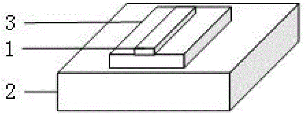
[0070] The test device involved in the present invention is such as figure 1 and figure 2 Shown.

[0071] Step one, connect the semiconductor device (1) with the semiconductor temperature calibration curve measuring device (3), put it in the thermostat (2), measure and establish the temperature-current-voltage temperature calibration surface of the semiconductor device through the electrical method, in the form image 3 Shown.

[0072] Step 2: The semiconductor device (1) and the semiconductor thermal resistance measuring instrument (4) measure the thermal resistance composition of the semiconductor device, and establish an RC thermal resistance model. In this example, the IGBT model of this type is as Figure 4 As shown, the estab...


PUM


Abstract

The invention discloses a junction temperature calibration method based on a mathematical filtering algorithm, and the junction temperature calibration method belongs to the field of electronic device tests. The traditional semiconductor device junction temperature measurement methods include an electrical method, an infrared method and the like. Due to the existence of theoretical errors and noise in the measurement process, the traditional methods cannot measure junction temperature of a semiconductor device accurately. The junction temperature calibration method regards a semiconductor device as a temporally discrete dynamic system with single input and double outputs, wherein the input is a thermal power matrix x<k-1><+> at a previous moment, and the double outputs are respectively junction temperature T<k><+> and a thermal power matrix x<k><+> at the moment. The junction temperature of the semiconductor device is effectively calibrated in real time through continuous recursion operation. The junction temperature calibration method is an algorithm for carrying out optimal estimation of system states by utilizing a linear system state equation and observing system outputs through system input. The algorithm can estimate states of the dynamic system from a series of data with noise under the condition that measured variance is known, and obtains data closer to a true value.

Description

Technical field [0001] The invention belongs to the field of electronic device testing, and is mainly applied to calibrate the measured junction temperature data based on the data measured by the electrical method and the data calculated by the RC model by using a mathematical filtering algorithm. Background technique [0002] With the rapid development of electronic technology, semiconductor devices have achieved considerable development. In recent years, with the rapid development of high-speed rail and wind power technologies, power devices have been widely used in these emerging fields. With the further miniaturization of power devices, the power density per unit area of ​​the device has been greatly improved compared with the original, which is accompanied by a further increase in the junction temperature of the device during operation. Excessively high junction temperature will cause the device characteristics to decrease, and at the same time, it is more likely to cause t...

Claims


Application Information

Patent Timeline
Patent Type & Authority Applications(China)
IPC IPC(8): G01R31/26
CPCG01R31/2601
Inventor 郭春生苏雅廖之恒冯士维朱慧
Owner BEIJING UNIV OF TECH
Learn More