Parallel optical assembly

An optical component and laser technology, applied in optical components, light guides, optics, etc., can solve the problems of poor assembly accuracy of electrical connectors and optical connectors, complex coupling process, large package size, etc., to achieve small package size, avoid damage, Good thermal matching performance

Active Publication Date: 2016-11-16
HISENSE & JONHON OPTICAL ELECTRICAL TECH CO LTD
View PDF6 Cites 9 Cited by
  • Summary
  • Abstract
  • Description
  • Claims
  • Application Information

AI Technical Summary

Problems solved by technology

[0005] The purpose of the present invention is to provide a parallel optical assembly to overcome the defects of complex coupling process, low assembly efficiency, large package size, poor assembly accuracy of electrical connectors and optical connectors existing in existing parallel optical assemblies

Method used


Image

  • Parallel optical assembly
  • Parallel optical assembly
  • Parallel optical assembly

Examples


Embodiment Construction

[0022] The specific embodiments of the present invention will be described in detail below, and it should be understood that the specific embodiments described here are only used to illustrate and explain the present invention, and are not intended to limit the present invention.

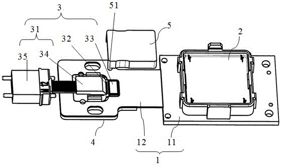
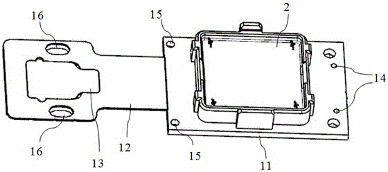
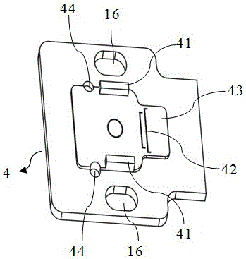
[0023] Such as Figure 1-Figure 4 As shown, the parallel optical assembly of this embodiment includes a PCB board 1, an electrical connector 2 and an optical connector 3 installed on the PCB board 1, and the optical connector 3 includes an FA fiber array assembly 31, a VCSEL laser or a PD detector 32 and Drive chip 33, PCB board 1 comprises rigid PCB board part 11 and flexible PCB board part 12, electrical connector 2 is arranged on the rigid PCB board part 11; The metal reinforcement plate 4 is provided with two parallel FA fixed bosses 41, a VCSEL laser or PD detector positioning identification area 42 and a drive chip positioning identification area 43, and the VCSEL laser or PD detector position...


PUM


Abstract

The invention discloses a parallel optical assembly. The PCB of the parallel optical assembly comprises a rigid PCB part and a flexible PCB part; the flexible PCB part can be folded or bended; an optical connector is arranged on a metal reinforcement plate in fixed connection with the flexible PCB part. In a packaging process, the optical connector and the metal reinforcement plate can bend or fold with the flexible PCB part, allowing the optical connector of an optical port packaging part to arrive at a most convenient assembling angle and position so as to realize rapid assembling, meanwhile helping reducing a packaging dimension, facilitating component high density distribution, and enhancing an adaptive capacity to environment. The parallel optical assembly can utilize the bending characteristic of the flexible PCB part to realize the overlapping installation of the parallel optical assembly, and guarantee optical connector and electric connector assembling precision so as to realize a compact structure of the parallel optical assembly; the packaging dimension is small, thereby facilitating the application of a parallel optical assembly high density integration communication system.

Description

technical field [0001] The invention relates to the technical field of optical fiber communication, in particular to a parallel optical component. Background technique [0002] With the increasingly higher requirements for communication bandwidth in the field of optical fiber communication, the application of multi-channel parallel optical fiber transmission or parallel optical interconnection is becoming more and more extensive. In order to realize multi-channel parallel optical interconnection, multi-channel parallel optical transceiver modules are usually used Perform multiple parallel optical interconnections. [0003] Compared with single-channel modules, parallel modules require higher component density, smaller package size and weight, and lower energy consumption. At the same time, thermal design, electromagnetic interference shielding design, packaging process design, photoelectric coupling design and circuit design There are higher requirements. The perfect struc...

Claims


Application Information

Patent Timeline
IPC IPC(8): G02B6/42H04B10/25
CPCG02B6/4202G02B6/4249G02B6/4281H04B10/25
Inventor 王永才孙阳辉姜瑜斐庄荣华
Owner HISENSE & JONHON OPTICAL ELECTRICAL TECH CO LTD
Why Eureka
Try Eureka