
Electrodeless ultraviolet lamp

An extreme ultraviolet and light bulb technology is applied in the field of electrodeless ultraviolet lamps, which can solve the problems of short service life and ultraviolet lamp sputtering.

Inactive Publication Date: 2016-11-16
ANHUI JOYFULL INFORMATION SCI & TECH
View PDF15 Cites 1 Cited by
  • Summary
  • Abstract
  • Description
  • Claims
  • Application Information

AI Technical Summary

Problems solved by technology

[0003] Traditional UV lamps have sputtering and short service life

Method used


Image

  • Electrodeless ultraviolet lamp

Examples


Embodiment Construction

[0013] Below in conjunction with accompanying drawing, the present invention will be further described.

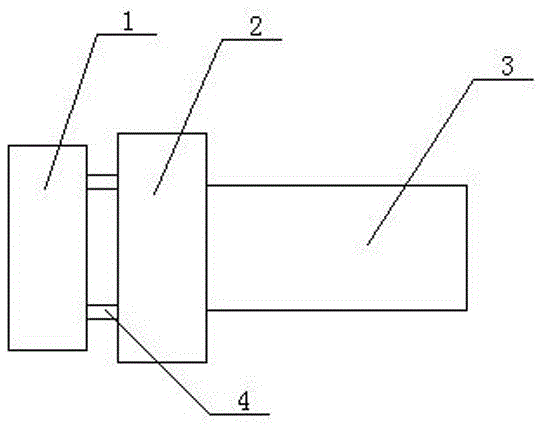
[0014] see figure 1 As shown, the technical solution adopted in this specific embodiment is: it includes an external cavity coupler 1, a quartz bulb 3 and a microwave generator 2; a heat pipe is arranged between the external cavity coupler 1 and the microwave generator 2 4; The quartz bulb 3 is provided with metal tribute and inert gas;

[0015] Described inert gas is argon;

[0016] The quartz bulb 3 is a rectangular closed bulb.

[0017] The external cavity coupler in this specific embodiment is arranged on the outside, which has a good heat dissipation effect, and the heat pipe can also dissipate the heat well, so the heat dissipation effect is good and the service life is long.

[0018] After adopting the above structure, the beneficial effects of the present invention are: the electrodeless ultraviolet lamp of the present invention has no sputtering phenomenon, goo...


PUM


Abstract

The invention relates to an electrodeless ultraviolet lamp and belongs to the technical field of an ultraviolet lamp. The electrodeless ultraviolet lamp comprises an external chamber coupler, a quartz lamp bulb and a micro wave generator, wherein a heat conduction tube is arranged between the external chamber coupler and the micro wave generator, and the quartz lamp bulb is internally provided with mercury and inert gas. The electrodeless ultraviolet lamp has advantages of no sputtering phenomenon, good heat radiation, long service life, high efficiency, energy-saving performance, simple structure, reasonable setting and low making cost.

Description

technical field [0001] The invention relates to the technical field of ultraviolet lamps, in particular to an electrodeless ultraviolet lamp. Background technique [0002] The electrodeless discharge light source is a new generation of gas discharge light source. It completely breaks through the light-emitting mechanism and design concept of the traditional light source in the light-emitting mechanism, and becomes a revolution in the development history of other discharge light sources. Since this type of light source has no electrodes, it will not produce blackening caused by electrode oxidation, loss and sealing problems like other discharge light sources. [0003] Conventional UV lamps have sputtering and short service life. Contents of the invention [0004] The object of the present invention is to provide an electrodeless ultraviolet lamp with simple structure, reasonable design and convenient use, aiming at the defects and deficiencies of the prior art. [0005] I...

Claims


Application Information

Patent Timeline
IPC IPC(8): H01J65/04H01J61/52
CPCH01J65/04H01J61/52
Inventor 朱卫国陈彬夏亦平
Owner ANHUI JOYFULL INFORMATION SCI & TECH
Learn More