Communication-in-motion small-sized antenna dehumidifier

A technology of mobile communications and dehumidifiers, applied in the direction of deicing/drying devices, etc., can solve the problems of affecting the normal operation of radome components, large temperature differences of radome, and radome is easy to condense and accumulate water, so as to facilitate popularization and use , Convenient processing and production, improve the condensation effect

Active Publication Date: 2016-11-16
SATPRO MEASUREMENT & CONTROL TECH
View PDF9 Cites 4 Cited by
  • Summary
  • Abstract
  • Description
  • Claims
  • Application Information

AI Technical Summary

Problems solved by technology

[0002] At present, with the development of science and technology, the communication antenna in motion is developing towards the compact type. The communication antenna in motion includes the radome and various components arranged in the radome. In order to ensure the normal operation of the various components in the radome, the radome It is made airtight and waterproof, which leads to large temperature and pressure differences inside and outside the radome
In particular, the internal temperature of the radome is high when the ship-borne mobile communication antenna is sailing on the sea surface, and the external temperature of the radome is low. The structure is compact and the space is small. At present, the dehumidifiers on the market are generally large in size and expensive, so they are not suitable for use in the radome.
Therefore, there is a lack of a small dehumidifier for mobile antennas with simple structure, reasonable design, and small volume. And discharge the radome, keep the air in the radome dry, and ensure that the working environment of each component is good

Method used


Image

  • Communication-in-motion small-sized antenna dehumidifier
  • Communication-in-motion small-sized antenna dehumidifier
  • Communication-in-motion small-sized antenna dehumidifier

Examples


Embodiment Construction

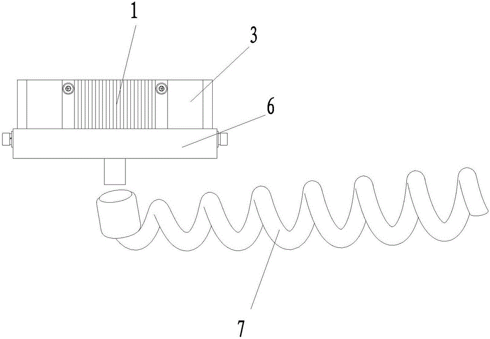
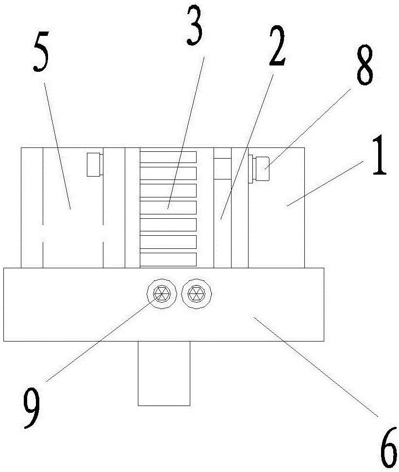
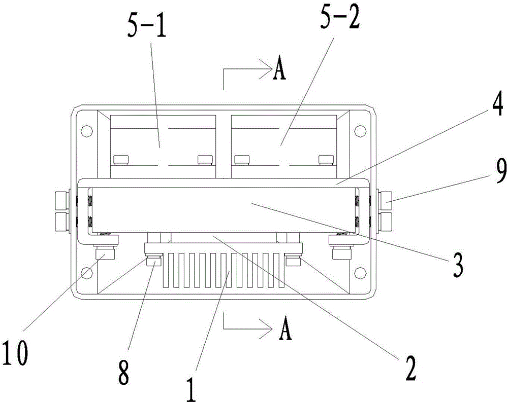
[0036] Such as figure 1 , figure 2 with image 3 As shown, the present invention includes a housing 6, a dehumidification mechanism arranged in the housing 6, and a drain pipe 7 arranged at the bottom of the housing 6. The dehumidification mechanism includes a condensation fin 1, a cooling fin 2 and a cooling fin connected in sequence. 3. The cooling surface of the refrigerating sheet 2 is attached to the flat surface of the condensing sheet 1, the heating surface of the refrigerating sheet 2 is attached to the heat sink 3, and the cooling sheet 3 is provided with a fan 5, and the condensing sheet 1, The refrigerating fins 2, the cooling fins 3 and the fan 5 are all arranged in parallel along the width direction of the casing 6, the casing 6 is a casing with an opening, the length of the casing 6 is 115cm-120cm, and the casing 6 The width of the casing 6 is 79cm-84cm, and the height of the housing 6 is 25cm-30cm.

[0037] In the actual use process, the upper and lower part...


PUM


Abstract

The invention discloses a communication-in-motion small-sized antenna dehumidifier comprising a shell body, a dehumidifying mechanism arranged in the shell body and an exhaust water pipe arranged on a bottom part of the shell body, wherein the dehumidifying mechanism comprises a condensation sheet, a refrigeration sheet and a heat dissipation sheet that are orderly connected with each other; a refrigeration surface of the refrigeration sheet adheres to a flat surface of the condensation sheet, a heating surface of the refrigeration sheet adheres to the heat dissipation sheet, and a fan is arranged on the heat dissipation sheet; the condensation sheet, the refrigeration sheet, the heat dissipation sheet and the fan are arranged in a width direction of the shell body in a parallel manner; the shell body is provided with an opening. The communication-in-motion small-sized antenna dehumidifier is simple in structure, reasonable in design, small in size, and low in cost; the communication-in-motion small-sized antenna dehumidifier is convenient to install; via arrangement of the dehumidifying mechanism, water vapor in humid air in an antenna housing can be turned into condensed water which can be discharged from the antenna housing, air in the antenna housing can be kept dry, that each component can work in a good environment can be ensured, and strong practicality is realized.

Description

technical field [0001] The invention belongs to the technical field of dehumidification equipment for mobile communication antennas, and in particular relates to a small dehumidifier for mobile communication antennas. Background technique [0002] At present, with the development of science and technology, the communication antenna in motion is developing towards the compact type. The communication antenna in motion includes the radome and various components arranged in the radome. In order to ensure the normal operation of the various components in the radome, the radome It is made airtight and waterproof, which leads to large temperature difference and pressure difference inside and outside the radome. In particular, the internal temperature of the radome is high when the ship-borne mobile communication antenna is sailing on the sea surface, and the external temperature of the radome is low. With compact structure and small space, the dehumidifiers currently on the market...

Claims


Application Information

Patent Timeline
Patent Type & Authority Applications(China)
IPC IPC(8): H01Q1/02
CPCH01Q1/02
Inventor 党创锋孙昀张学文
Owner SATPRO MEASUREMENT & CONTROL TECH
Why Eureka
Try Eureka