Power distribution cabinet

A power distribution cabinet and cabinet technology, applied in substation/distribution device shell, substation/switchgear board/panel/desk, anti-seismic equipment, etc. Problems such as poor sealing performance of power distribution cabinets, to achieve the effect of reducing electrical equipment disconnection, good prevention, and convenient maintenance

Inactive Publication Date: 2016-11-16
PENGLAI POWER SUPPLY CO OF STATE GRID SHANDONG ELECTRIC POWER CO
View PDF6 Cites 17 Cited by
  • Summary
  • Abstract
  • Description
  • Claims
  • Application Information

AI Technical Summary

Problems solved by technology

[0002] In the existing power distribution cabinet, the equipment is usually installed directly on the inner wall of the power distribution cabinet. During the installation process, the power distribution cabinet will be damaged to a certain extent, so that the sealing performance of the power distribution cabinet is not good. , the internal electrical equipment is prone to open circuit, due to the overall installation, the electrical equipment is inconvenient to disassemble, resulting in inconvenient maintenance

Method used


Image

  • Power distribution cabinet

Examples


Embodiment 1

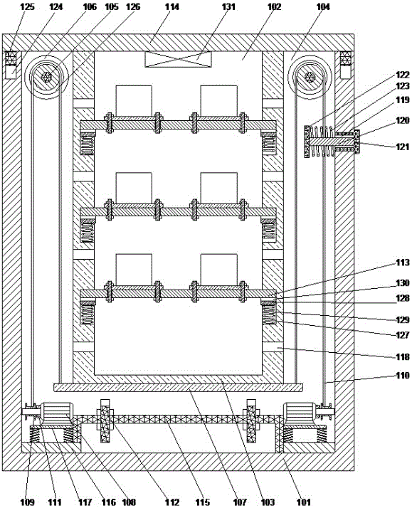
[0019] Such as figure 1 As shown, a power distribution cabinet includes an outer cabinet body 101 with an opening 102 on the upper part, and an inner cabinet body 103 for installing switchgear is arranged inside the outer layer cabinet body 101. Card slots 127 are respectively arranged on the two opposite end faces of the inner wall of the layer cabinet body 103, and a partition plate 113 is arranged inside the inner layer cabinet body 103, and the two ends of the partition plate 113 are inserted into the card slots respectively. Inside the groove 127, a buffer strip 128 is arranged on the upper end surface inside the said card slot 127, and a buffer spring 129 is arranged between the lower end surface of said buffer strip 128 and said card groove 127. The lower end surface of the plate 113 is attached to the upper end surface of the buffer strip 128, and there is a cavity 104 between the inner cabinet body 103 and the outer cabinet body 101, inside the cavity 104 Two rotatin...

Embodiment 2

[0024] In this embodiment, in order to facilitate the installation of the drive motor, preferably, the two ends of the mounting plate 115 are respectively provided with a horizontal plate 116, and the horizontal plate 116 is welded on the upper end surface of the bottom of the outer cabinet body 101 , the drive motor 108 is detachably connected to the horizontal plate 116 . By installing the driving motor on a horizontal plate, damage to the outer cabinet body during installation of the driving motor can be avoided, and at the same time, the disassembly of the driving motor can be facilitated.

[0025]In order to improve the anti-seismic performance of the driving motor, in this embodiment, preferably, a support plate 117 is provided above the horizontal plate 116, and the support plate 117 and the horizontal plate 116 are mutually connected by at least four high-strength springs. The drive motor 108 is fixedly connected to the upper end surface of the support plate 117 by bol...

Embodiment 3

[0027] In this embodiment, in order to improve the sealing performance of the overall structure and prevent the moisture outside the outer cabinet from entering the inner side of the outer cabinet during the rainy summer season, preferably, the outer cabinet 101 is close to the end cover 114 is provided with a pressure relief hole 119 on the side wall of one end, and a pressure relief rod 120 is provided in the pressure relief hole 119, and a pressure relief rod 120 is provided on the pressure relief rod 120 that can be plugged into the pressure relief hole 119 The inner sealing ring 121 is provided with a circular plate 122 inside the pressure relief hole 119, the pressure relief rod 120 is fixedly connected to the circular plate 122, and the pressure relief rod 120 is sleeved with Return spring 123, one end of the return spring 123 is fixedly connected to the circular plate 122, and the other end is fixedly connected to the inner wall of the outer cabinet body 101, and the re...


PUM


Abstract

The invention discloses a power distribution cabinet. The power distribution cabinet comprises an outer layer cabinet body having an opening in the upper part, wherein an inner layer cabinet body which is used for mounting switch equipment is arranged on the inner side of the outer layer cabinet body; clamping grooves are formed in the opposite two end planes of the inner wall of the inner layer cabinet body; partition plates are arranged on the inner side of the inner layer cabinet body; the two ends of the partition plates are inserted in the inner sides of the corresponding clamping grooves; buffer strips are arranged on the upper end planes on the inner sides of the clamping grooves; buffer springs are arranged between the lower end planes of the buffer strips and the clamping grooves; the lower end planes of the partition plates are attached to the upper end planes of the corresponding buffer strips; a cavity is formed between the inner layer cabinet body and the outer layer cabinet body; and two parallel rotary shafts are arranged on the inner side of the cavity. According to the power distribution cabinet, the partition plates are inserted in he inner side of the inner layer cabinet body to realize the installation of the partition plates; the equipment is mounted on the corresponding partition plates; and when the equipment is maintained, the partition plates are drawn out of the inner layer cabinet body, so that the equipment can be installed and maintained conveniently.

Description

technical field [0001] The invention relates to a power distribution cabinet. Background technique [0002] In the existing power distribution cabinet, the equipment is usually installed directly on the inner wall of the power distribution cabinet. During the installation process, the power distribution cabinet will be damaged to a certain extent, so that the sealing performance of the power distribution cabinet is not good. , The internal electrical equipment is prone to open circuit. Due to the overall installation method, the electrical equipment is inconvenient to disassemble, resulting in inconvenient maintenance. Contents of the invention [0003] The purpose of the present invention is to provide a power distribution cabinet, which can improve the problems existing in the prior art, and realize the installation of the partition board by inserting the partition board inside the inner cabinet body, and install the equipment on the partition board , when maintenance i...

Claims


Application Information

Patent Timeline
Patent Type & Authority Applications(China)
IPC IPC(8): H02B1/30H02B1/54H02B1/015
CPCH02B1/015H02B1/30H02B1/54
Inventor 孙剑波吴佳芮方振伟王志凤王岩张远铭孙凯吴超孙韬赵文斌
Owner PENGLAI POWER SUPPLY CO OF STATE GRID SHANDONG ELECTRIC POWER CO
Why Eureka
Try Eureka