Heat dissipation structure of transmitter

A technology of heat dissipation structure and transmitter, which can be applied to structural parts of electrical equipment, modification through conduction and heat transfer, cooling/ventilation/heating transformation, etc., which can solve problems such as shortened lifespan, increased weight of carrier aircraft, and impact of radio frequency chips on performance. , to achieve the effect of ultra-light weight, shorten the thermal conduction path, and increase the thermal conduction area

Inactive Publication Date: 2016-11-16
孙海华
View PDF7 Cites 3 Cited by
  • Summary
  • Abstract
  • Description
  • Claims
  • Application Information

AI Technical Summary

Problems solved by technology

Risk analysis of the heat dissipation path of Tx machine B: 1. Installing a fan increases the weight of the carrier, the short life of the fan motor indirectly shortens the life of the Tx, the vibration makes the carrier unstable, and the consumed current directly shortens the service life of the power supply equipment; 2. , Only the PA chip is used for heat dissipation, and the RF chip is also a heating element, which is ignored, causing the performance of the RF chip to be affected at high temperatures

Method used


Image

  • Heat dissipation structure of transmitter
  • Heat dissipation structure of transmitter
  • Heat dissipation structure of transmitter

Examples


Embodiment Construction

[0022] The specific implementation manners of the present invention will be further described in detail below in conjunction with the accompanying drawings and embodiments. The following examples are used to illustrate the present invention, but are not intended to limit the scope of the present invention.

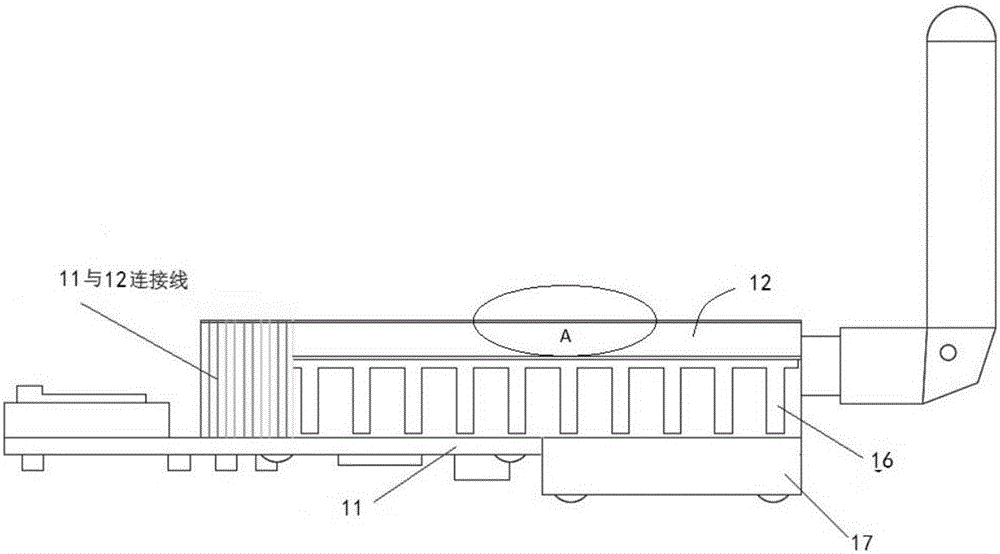
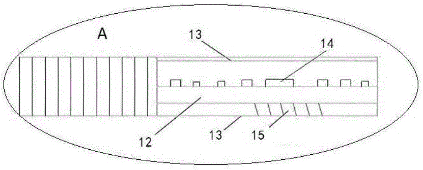
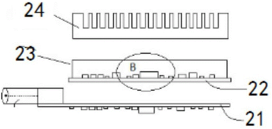
[0023] Such as Figure 5 and 6 As shown, the heat dissipation structure of the transmitter of the present invention includes an integrated circuit board 1 with a thickness of 0.4 to 1.0 mm. The integrated circuit board 1 is thinner than the existing integrated circuit board, so that the heat conduction path can be shortened. Equipped with power amplifier 2, radio frequency chip and power chip, the front of the integrated circuit board is mounted with a shielding cover 3, only 4 corners are soldered firmly, and the shielding cover 3 is thickly protected to avoid greater losses caused by the aircraft model falling and damaging the device , is also convenient for disassembl...


PUM


Abstract

The invention aims at providing a heat dissipation structure, with simple structure and good heat dissipation effect, of a transmitter. The heat dissipation structure comprises an integrated circuit board, wherein a power amplifier, a radio frequency chip and a power chip are arranged on the front of the integrated circuit board; metal foil is paved on the back of the integrated circuit board; pores through which bottoms of the power amplifier, the radio frequency chip and the power chip communicate with the metal foil are respectively formed in the integrated circuit board; each pore is filled with heat-conductive adhesives; and an aluminum heat sink is fixed on the back of the integrated circuit board by a connecting piece, and tightly attached to the metal foil.

Description

technical field [0001] The invention relates to a casing or a structural part of an electric device, in particular to a heat dissipation structure of a transmitter. Background technique [0002] The wireless audio and video transmission system is a transceiver with the function of wirelessly transmitting and receiving images and sounds. It mainly includes a transmitter (Tx) and a receiver (Rx). It transmits and receives through the antenna under the checked frequency. The shared common frequencies are 2.4GHz and 5.8GHz. GHz band. Among them, the transmitter (Tx) is composed of a radio frequency module and a power module and has a stacked structure. The radio frequency module includes a radio frequency circuit board (PCB) and a radio frequency chip arranged on the radio frequency circuit board (PCB). Since the output power of a general radio frequency chip Relatively low (such as 10Mw), it cannot meet the product performance requirements, so the power amplifier (PA) is usual...

Claims


Application Information

Patent Timeline
Patent Type & Authority Applications(China)
IPC IPC(8): H04B1/036H04B1/04H05K7/20
CPCH04B1/036H04B1/04H04B2001/0408H05K7/2039H05K7/205
Inventor 孙海华
Owner 孙海华
Why Eureka
Try Eureka