
Magnetic inflatable bottle holder for soda dispenser and soda dispenser

A technology for holding devices and inflatable bottles, applied in beverage preparation devices, applications, kitchen utensils, etc., can solve the problems of inconvenient opening and tightening of bottle caps, inconvenient release of pressure threshold, inconvenient use and replacement, etc., to achieve simple structure and easy Controlled, easy-twist effect

Active Publication Date: 2021-04-20
真上康国际有限公司
View PDF9 Cites 0 Cited by
  • Summary
  • Abstract
  • Description
  • Claims
  • Application Information

AI Technical Summary

Problems solved by technology

[0002] At present, the soda production equipment on the market generally uses CO 2 Inflatable cylinders are inflated, but when the gas volume is not enough to meet the user's requirements, it is usually necessary to replace another gas cylinder to continue to inflate. In this way, after the inflatable cylinder is used up, the operation of taking out and inserting the inflatable cylinder is performed, while currently on the market CO 2 Inflatable soda machines are all hand or clip to keep the CO 2 Inflatable bottles are inconvenient to use and replace, and the replacement efficiency is low
[0003] In addition, the design of the pressure relief valve in the safety mechanism of the soda machine on the market is to use a spring structure. Such a mechanism is not convenient for adjusting and controlling the release pressure threshold.
[0004] Furthermore, the existing soda bottle body and bottle cap are multi-position cylindrical (that is, the cross-section is circular). Such a design not only tends to slide when screwing the bottle cap and holding the bottle body, but is not easy to open and close. The cap is tight and not easy to hold
In addition, when the soda bottle is placed horizontally on a flat surface such as a table, it is easy to roll

Method used


Image

  • Magnetic inflatable bottle holder for soda dispenser and soda dispenser
  • Magnetic inflatable bottle holder for soda dispenser and soda dispenser
  • Magnetic inflatable bottle holder for soda dispenser and soda dispenser

Examples


Embodiment Construction

[0045] The present invention will be described in detail below in conjunction with the accompanying drawings and embodiments.

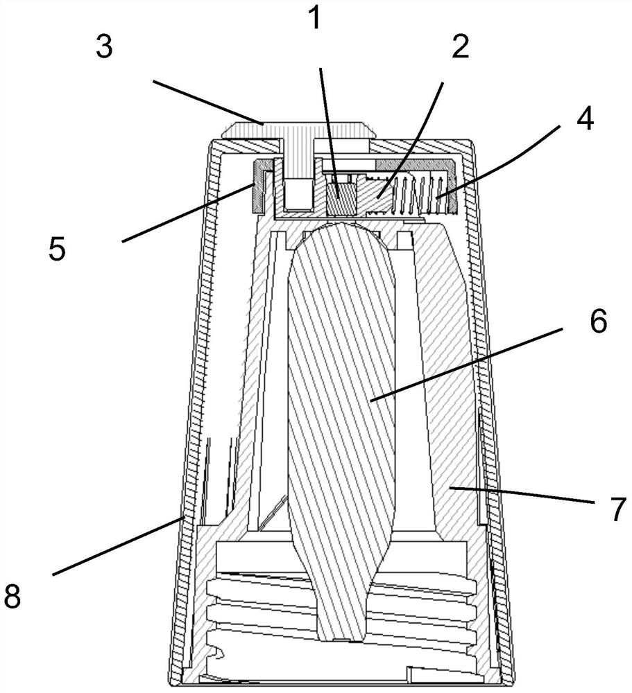
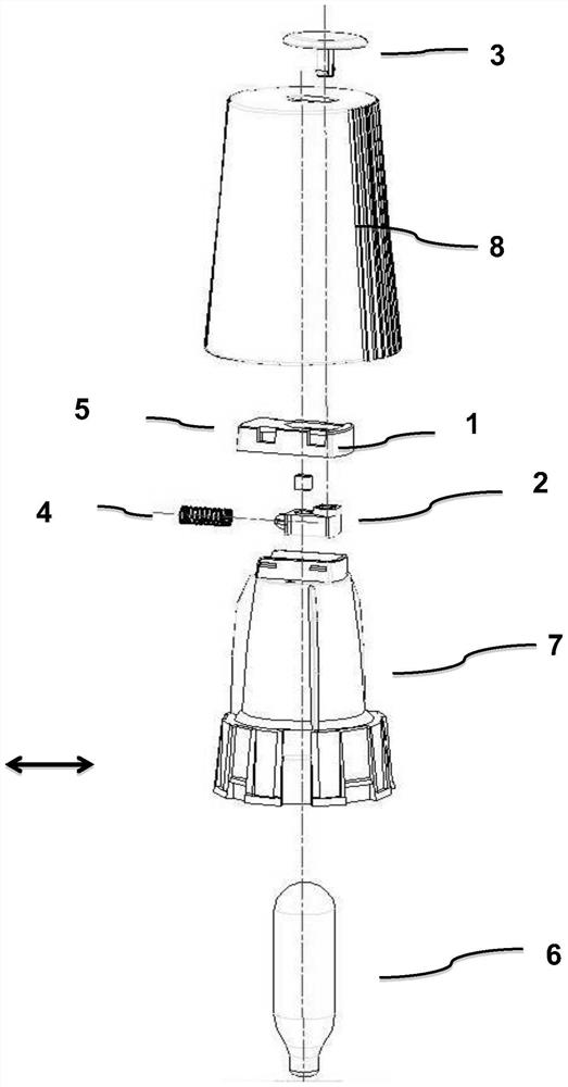
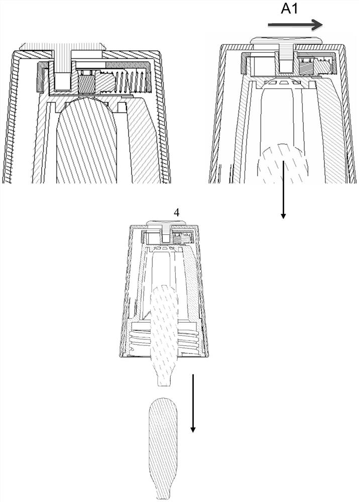
[0046] like Figure 1-3 As shown, the present invention provides a magnetic refill bottle holder for a soda dispenser. figure 1 is a cross-sectional view of a magnetic inflatable bottle holding device according to an embodiment of the present invention, figure 2 is an exploded view of a magnetic gas-filled bottle holding device according to an embodiment of the present invention, image 3 It is a schematic diagram of the working principle of the magnetic inflatable bottle holding device according to the embodiment of the present invention. As shown in the figure, the magnetic inflatable bottle holding device includes a magnet 1 , a translation mechanism 2 and a trigger switch 3 . The translation mechanism 2 has two grooves, one for accommodating the magnet 1 and the other for inserting the trigger switch 3 . The magnetic gas bottle holding device ...


PUM


Abstract

The invention relates to a holding device for a magnetic inflatable bottle used in a soda machine and the soda machine. Magnetic bottle holder that uses magnetism to hold and release CO 2 Inflatable bottle for easy CO 2 The replacement of the gas bottle is easy to operate and has high replacement efficiency. The safety mechanism of the soda machine of the present invention includes more than two pressure release channels, the pressure release is fast and balanced, and the safety is higher, and the release pressure threshold is adjusted by using the elasticity of the silicone sleeve and the change of the position and diameter of the release hole, the structure is simple, and Easy to control. The soda bottle of the soda water machine of the present invention has a longitudinal truncated plane on the bottle cap and the outer cylindrical surface of the bottle body, so that it is easy to twist and hold, the design is economical, and it is not easy to roll when placed horizontally. At the same time, the large mouth diameter makes filling and pouring easier.

Description

technical field [0001] The present invention relates to a soda water making device, such as a soda water machine, in particular to an air bottle holding device and a safety mechanism therein. Background technique [0002] At present, the soda production equipment on the market generally uses CO 2 Inflatable cylinders are inflated, but when the gas volume is not enough to meet the user's requirements, it is usually necessary to replace another gas cylinder to continue to inflate. In this way, after the inflatable cylinder is used up, the operation of taking out and inserting the inflatable cylinder is performed, while currently on the market CO 2 Inflatable soda machines are all hand or clip to keep the CO 2 Inflatable bottles are very inconvenient to use and replace, and the replacement efficiency is low. [0003] In addition, the design of the pressure release valve in the safety mechanism of the soda machine on the market is all using a spring structure, and such a mech...

Claims


Application Information

Patent Timeline
Patent Type & Authority Patents(China)
IPC IPC(8): A47J31/00A47J31/44
Inventor 陆婉仪
Owner 真上康国际有限公司
Learn More