Automatic cleaning machine for shaft-class parts

A technology for automatic cleaning machines and shaft parts, which is applied in dryers, cleaning methods and utensils, cleaning methods using liquids, etc. problem, to achieve the effect of significant cleaning effect, small footprint, and clean cleaning

Inactive Publication Date: 2016-11-23
重庆南雁实业集团龙剑机械制造有限公司
View PDF7 Cites 2 Cited by
  • Summary
  • Abstract
  • Description
  • Claims
  • Application Information

AI Technical Summary

Problems solved by technology

The existing cleaning method is to place a number of gear shafts on the rack for washing, which is almost all done manually, the cleaning efficiency is low, and the labor intensity of the workers is high
At the same time, the above washing method can only clean the s

Method used


Image

  • Automatic cleaning machine for shaft-class parts
  • Automatic cleaning machine for shaft-class parts
  • Automatic cleaning machine for shaft-class parts

Examples


Embodiment Construction

[0020] Below in conjunction with accompanying drawing and embodiment the present invention will be further described:

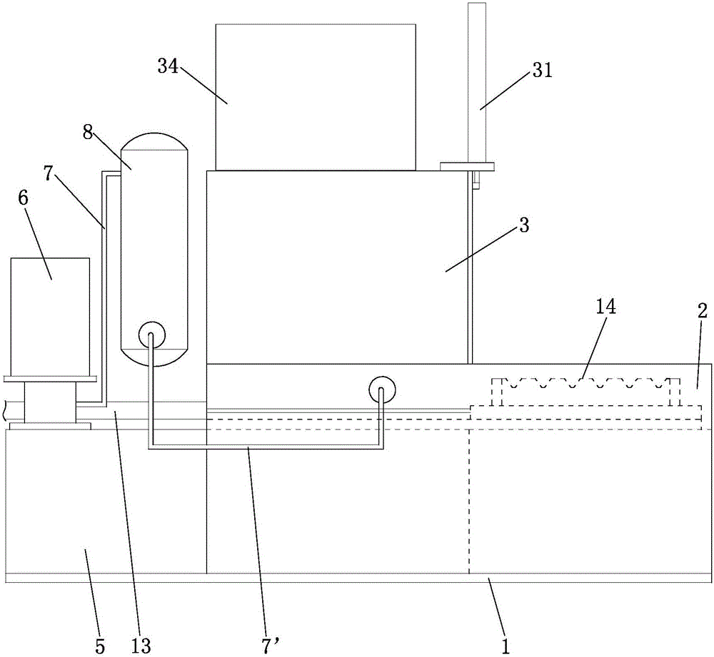
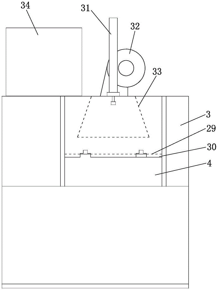
[0021] Such as figure 1 , figure 2 , image 3 As shown, an operation warehouse 2 is set on the top of the front end of the bed 1, and the upper end of the operation warehouse 2 is open. A cleaning chamber 3 is arranged above the middle part of the bed 1 , and a material inlet and outlet 4 is provided at the front end of the cleaning chamber 3 . The top of inlet and outlet opening 4 is covered by fixed door 29, and movable door 30 is provided with in the place ahead of fixed door 29, and the two ends of this movable door 30 are positioned at the guide chute of corresponding setting, the middle part of movable door 30 tops and vertical cylinder 31 The piston rod is connected, and the cylinder body of the vertical cylinder 31 is fixed on the top of the cleaning chamber 3 front ends. Under the action of the vertical cylinder 31, the dodge door 30 can be rais...


PUM


Abstract

The invention discloses an automatic cleaning machine for shaft-class parts. A water collecting main pipe is connected with a row of sprayer heads sequentially arranged from front to back. A feeding cart is in sliding fit with two longitudinal guide rails through sliding blocks at the bottom of the feeding cart. A first supporting plate and a second supporting plate which are parallel left and right are arranged on the feeding cart. The row of sprayer heads are installed on the same sprayer head supporting frame which is in sliding fit with two first transverse guide rails through sliding blocks at the bottom of the sprayer head supporting frame. A longitudinal beam is arranged on the other side, opposite to the second supporting plate, of the first supporting plate and is a rectangular pipe. Guide sleeves are fixed to the front end and the rear end of the top surface of the longitudinal beam, and the axes of the guide sleeves are perpendicular to the longitudinal guide rails. Detection pins penetrate in the guide sleeves, and the tips of the detection pins perpendicularly face the first supporting plate. The automatic cleaning machine for shaft-class parts integrates the functions of cleaning and drying, and is convenient and fast to operate, high in automation degree, thorough in cleaning, obvious in cleaning effect, and capable of lowering cleaning cost and effectively improving production efficiency.

Description

technical field [0001] The invention belongs to the technical field of automobile parts processing, in particular to an automatic cleaning machine for shaft parts. Background technique [0002] The gear shaft is an important component of the automobile gearbox, which is used to support the gears so that the gears that mesh with each other can transmit power smoothly. After the gear shaft is machined, it is inevitable that there will be oil, iron filings and other sundries, so the cleaning process is essential. The existing cleaning method is to place a number of gear shafts on the rack for washing, which is almost all done manually, the cleaning efficiency is low, and the labor intensity of the workers is high. Simultaneously, above-mentioned flushing method can only clean sundries on the surface of the gear shaft, and the inner hole of the gear shaft is difficult to be flushed due to a certain length, so the cleaning is not thorough and the cleaning effect is not ideal, ma...

Claims


Application Information

Patent Timeline
IPC IPC(8): B08B3/02B08B3/08B08B3/14B08B13/00F26B21/00
CPCB08B3/02B08B3/08B08B3/14B08B13/00F26B21/00
Inventor 何剑
Owner 重庆南雁实业集团龙剑机械制造有限公司
Why Eureka
Try Eureka