Automatic turning machine tool

A technology of automatic lathes and machine tools, applied in the direction of automatic lathes/semi-automatic lathes, turning equipment, turning equipment, etc., can solve the problems of increasing auxiliary processing time, increasing labor intensity of workers, affecting production efficiency, etc., to save auxiliary processing time and production. The effect of high efficiency and reduced labor intensity

Inactive Publication Date: 2016-11-23
郭世怡
View PDF8 Cites 22 Cited by
  • Summary
  • Abstract
  • Description
  • Claims
  • Application Information

AI Technical Summary

Problems solved by technology

Processes that require high precision are usually completed on different CNC machine tools, but simple processes such as chamfering also require CNC lathes to complete, which will not only cause a lot of waste of CNC equipment, but also Workers are required to transfer workpieces between different lathes, which virtually increases the auxiliary processing time, increases the labor intensity of workers, and seriously affects production efficiency

Method used


Image

  • Automatic turning machine tool
  • Automatic turning machine tool

Examples


Embodiment Construction

[0018] The following describes the technical solutions in the embodiments of the present invention clearly and completely with reference to the accompanying drawings in the embodiments of the present invention. Obviously, the described embodiments are only a part of the embodiments of the present invention, rather than all the embodiments. Based on the embodiments of the present invention, all other embodiments obtained by those of ordinary skill in the art without creative work shall fall within the protection scope of the present invention.

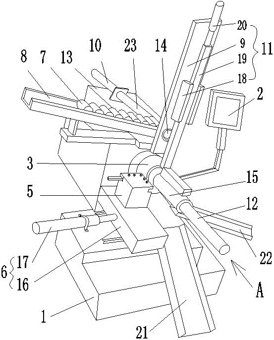
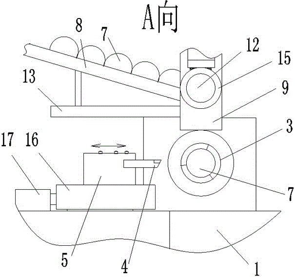
[0019] Such as figure 1 , 2 An automatic turning machine tool shown includes a machine base 1, a control panel 2, and a turning device and a loading device connected to the control panel 2. The turning device includes a motor-driven chuck 3 and a tool with a turning tool 4. The seat 5, the knife seat 5 is connected with the radial feeding device 6, the feeding device is arranged above the chuck 3; the feeding device includes a feeding chute...


PUM


Abstract

The invention discloses an automatic turning machine tool, and relates to the technical field of cold machining equipment. The automatic turning machine tool comprises a machine base, a turning device connected with a control panel and a feeding device connected with the control panel; the turning device comprises a chuck driven by a motor and a knife base provided with a turning knife and connected with a radial supply device, and the feeding device is arranged above the chuck; the feeding device comprises a feeding chute, a stand column and a pushing mechanism, wherein the stand column and the pushing mechanism are arranged on the two sides of the bottom end of the chute; a material via hole is formed in the bottom of the stand column, a lifting mechanism is arranged on the other side of the stand column, and a maternal storage hole is formed in the bottom of the lifting mechanism; and a feeding mechanism connected with the maternal storage hole is arranged at the bottom of the lifting mechanism. The maternal storage hole is lifted by the lifting mechanism to be coincide with the material via hole of the stand column, workpieces at the bottom of the feeding chute are pushed by the pushing mechanism into the maternal storage hole, the lifting mechanism descends to enable the workpieces in the maternal storage hole to descend to the position of a clamping claw of the chuck, the feeding mechanism drives a stretchable rod to push the workpieces from the material storage hole into the clamping claw of the chuck, and the feeding device is matched with the turning device through the control panel so as to achieve feeding, clamping and turning of the workpieces.

Description

Technical field [0001] The invention relates to the technical field of cold working equipment, in particular to an automatic turning machine tool. Background technique [0002] At present, for the processing of workpieces with small length and diameter, in order to adapt to mass production, sequential processing is usually performed. For example, for the processing of worm products, the process flow is: bar sawing and cutting-rough turning-drilling-fine turning-turning 30° chamfering-milling worm thread-deburring-heat treatment. Processes with high precision requirements are usually completed on different CNC machine tools, but simple processes such as car chamfering also need to be completed by CNC lathes, which will not only cause great waste of CNC equipment, but also Workers are required to transfer the workpieces between different lathes, which invisibly increases the auxiliary processing time, increases the labor intensity of the workers, and also seriously affects the pro...

Claims


Application Information

Patent Timeline
Patent Type & Authority Applications(China)
IPC IPC(8): B23B7/12B23B15/00B23Q7/00B23Q7/04B23Q7/08
CPCB23B7/12B23Q7/006B23Q7/04B23Q7/08
Inventor 郭世怡
Owner 郭世怡
Why Eureka
Try Eureka