Welding burr scraping structure

A burr and rough cutting technology, applied in the direction of welding fittings, etc., can solve the problems that the protrusions at the weld are easily corroded, the overall strength of the weld is reduced, and the service life of the steel pipe is reduced, so as to improve the cutting efficiency and increase the predictability. Effects of cleaning up and reducing workload

Inactive Publication Date: 2016-11-23
CHONGQING YINGJIE SCI & TECH CO LTD
View PDF0 Cites 3 Cited by
  • Summary
  • Abstract
  • Description
  • Claims
  • Application Information

AI Technical Summary

Problems solved by technology

[0002] When the steel pipe is welded, a certain amount of burrs will be generated inside and outside the steel pipe near the weld seam, which will reduce the flow rate of the fluid in the pipe when the steel pipe is in use, and the protrusions at the weld seam will be easily corroded, which will lead to a decrease in the overall strength of the weld seam, reducing the The service life of the steel pipe is shortened; the traditional internal burr removal equipment mainly focuses on the removal of solder residue and protrusions around the weld seam and the weld seam, but the solder residue and protrusions scattered to other parts of the inner wall of the steel pipe during welding are not cleaned thoroughly.

Method used


Image

  • Welding burr scraping structure
  • Welding burr scraping structure
  • Welding burr scraping structure

Examples


Embodiment 1

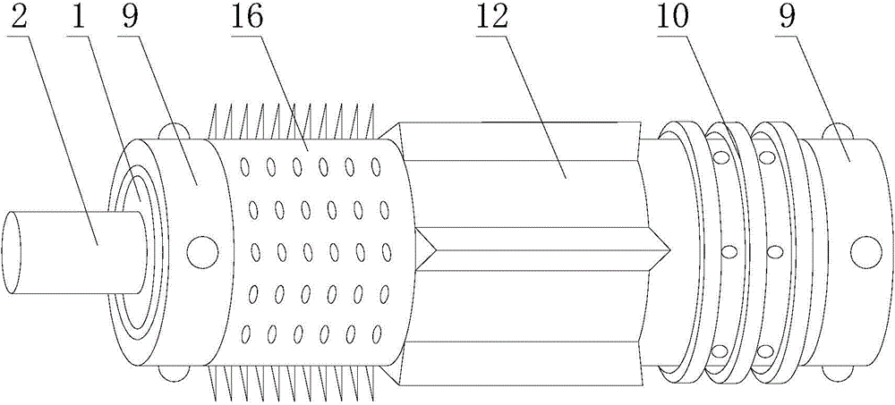
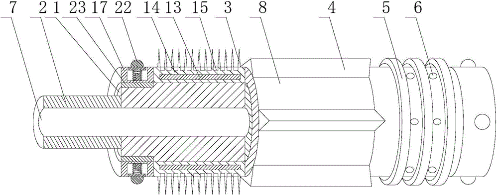
[0028] Such as Figure 1 to Figure 4As shown, the welding burr scraping structure includes a movable shaft 1 arranged horizontally and a connecting body 2 connected to the front end of the movable shaft 1 and arranged horizontally. The movable shaft 1 and the connecting body 2 are both hollow, and the two communicate with each other to form a water injection channel 7 , the front and rear sections of the movable shaft 1 are provided with a supporting part 9 through bearings 23, and the middle section of the movable shaft 1 is provided with a rough cutting part 10, a fine cutting part 12 and a cleaning part 16 successively from back to front; the rough cutting part 10 includes A plurality of annular retaining rings 5 ​​are sleeved on the movable shaft 1 at intervals, and a plurality of discharge holes 6 communicating with the water injection channel 7 are arranged between two adjacent annular retaining rings 5; The annular knife seat 8 on the movable shaft 1, the outer wall of ...


PUM


Abstract

The invention discloses a welding burr scraping structure. The welding burr scraping structure comprises a transversely arranged movable shaft and a connecting body which is connected with the front end of the movable shaft and arranged transversely. The movable shaft and the connecting body are both hollow and communicate with each other to form a water injection passage. The front section and the rear section of the movable shaft are each sleeved with a supporting portion through a bearing. A rough scraping portion, a fine scraping portion and a cleaning portion are arranged at the middle section of the movable shaft sequentially from back to front in a sleeving mode. When a blade meets large resistance, supporting bodies contract in installation holes under the receding of elastic deformation of elastic parts so that the position of the movable shaft in a steel pipe can be changed, the relative positions between the blade and burrs are indirectly changed, and the blade is buffered. In this way, the situation that serious hard collision occurs to the blade and then the blade is damaged is avoided. When resistance on the blade is gradually decreased, the supporting bodies return again under the supporting of elastic deformation of the elastic parts and limiting action of baffles. At the time, the movable shaft returns as well, and the distance between the blade and the inner wall of the steel pipe recovers accordingly, so that cutting work is conducted.

Description

technical field [0001] The invention relates to an argon arc welding machine auxiliary equipment, in particular to a welding burr scraping structure. Background technique [0002] When the steel pipe is welded, a certain amount of burrs will be generated inside and outside the steel pipe near the weld seam, which will reduce the flow rate of the fluid in the pipe when the steel pipe is in use, and the protrusions at the weld seam will be easily corroded, which will lead to a decrease in the overall strength of the weld seam, reducing the The service life of the steel pipe is shortened; the traditional internal burr removal equipment mainly focuses on the removal of solder residue and protrusions around the weld seam and the weld seam, but the solder residue and protrusions scattered to other parts of the inner wall of the steel pipe during welding are not cleaned thoroughly. . Contents of the invention [0003] The purpose of the present invention is to provide a welding ...

Claims


Application Information

Patent Timeline
Patent Type & Authority Applications(China)
IPC IPC(8): B23K9/32
Inventor 王建勇
Owner CHONGQING YINGJIE SCI & TECH CO LTD
Why Eureka
Try Eureka