Simple and practical mechanical arm

A kind of mechanical arm and practical technology, applied in the direction of manipulator, claw arm, chuck, etc., can solve the problems of manipulator clamping instability, complex structure, narrow clamping range, etc., and achieve simple structure, increased clamping range and convenient service Effect

Inactive Publication Date: 2016-11-23
XINGUANG NUMERICAL CONTROL TECH
View PDF10 Cites 9 Cited by
  • Summary
  • Abstract
  • Description
  • Claims
  • Application Information

AI Technical Summary

Problems solved by technology

[0003] The purpose of the present invention is to provide a simple and practical mechanical arm to solve the problems of complex structure, unstable clamping and narrow clamping range of the above-mentioned background technology

Method used


Image

  • Simple and practical mechanical arm

Examples


Embodiment Construction

[0012] The following will clearly and completely describe the technical solutions in the embodiments of the present invention with reference to the accompanying drawings in the embodiments of the present invention. Obviously, the described embodiments are only some, not all, embodiments of the present invention. Based on the embodiments of the present invention, all other embodiments obtained by persons of ordinary skill in the art without making creative efforts belong to the protection scope of the present invention.

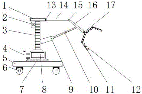
[0013] see figure 1 , the present invention provides a technical solution: a simple and practical mechanical arm, including a frame 1, a base 5, a support base 9, a second rotating layer 13 and an arm 16, a support rod 3 is fixedly installed under the frame 1, and the frame 1 is connected with the cylinder 8 through the support rod 3, and the travel switch 2 is fixedly installed on the left side of the support rod 3. The support rod 3 is a telescopic structure...


PUM


Abstract

The invention discloses a simple and practical mechanical arm which comprises a frame, a base, a supporting seat, a second rotary layer and an arm body. A supporting rod is fixedly installed under the frame, and the frame is connected with an air cylinder through the supporting rod. A travel switch is fixedly installed on the left side of the supporting rod. A telescopic rod is installed on the oblique upper portion of the supporting seat, and the supporting seat is connected with the arm body through the telescopic rod. A supporting arm is fixedly installed on the right side of the second rotary layer, and the frame is connected with the supporting arm through the second rotary layer. The arm body is connected with the supporting arm through a rotating device, and a wrist is installed on the oblique lower portion of the arm body. The arm body is connected with a manipulator through the wrist. According to the simple and practical mechanical arm, suckers are evenly arranged on the surface of the manipulator, when a round object is clamped, the object is sucked through the suckers, thereby being prevented from falling, unnecessary troubles are avoided, and the simple and practical mechanical arm is simple in structure and easy to operate.

Description

technical field [0001] The invention relates to the technical field of machining, in particular to a simple and practical mechanical arm. Background technique [0002] A manipulator is an automatic operating device that can imitate certain movement functions of the human hand and arm to grab, carry objects or operate tools according to a fixed program. The manipulator is the earliest industrial robot and the first modern robot. It can replace the heavy labor of people to realize the mechanization and automation of production, and can operate in harmful environments to protect personal safety. Therefore, it is widely used in machinery manufacturing, metallurgy, Electronics, light industry and atomic energy and other departments, but as far as the robotic arms currently on the market are concerned, there are still some problems that have been plagued by customers. For example, the structure is too complicated, the operation is difficult, and it cannot meet people's needs. It ...

Claims


Application Information

Patent Timeline
Patent Type & Authority Applications(China)
IPC IPC(8): B25J5/00B25J15/06B25J18/00
CPCB25J5/007B25J15/0683B25J18/00
Inventor 俞晓
Owner XINGUANG NUMERICAL CONTROL TECH
Why Eureka
Try Eureka