Pipeline inner wall spraying robot

A spraying robot and pipeline technology, applied in the field of robots, can solve the problems of lack of 4-axis linkage and restrictions on spraying methods, and achieve the effects of compact structure, long output stroke, and prevention of overheating

Inactive Publication Date: 2016-11-23
JIANGSU XINTU MACHINERY CO LTD
11 Cites 9 Cited by

AI-Extracted Technical Summary

Problems solved by technology

Although the spraying robot can accurately control the distance of the nozzle and the thickness of the spraying during spraying, it does not have...

Abstract

The invention relates to a pipeline inner wall spraying robot which comprises a base, a stand column and a multi-section servo electric cylinder, wherein the stand column is vertically arranged on the base, and the multi-section servo electric cylinder is arranged on one side of the stand column. The stand column is vertically and fixedly connected to a sliding block A on a linear guide rail A. The middle portion of the side face, across the linear guide rail A, of the stand column is provided with a groove in the height direction of the stand column, and the upper end face of the groove is reserved. A Z-axis box is fixed to a sliding block B of a liner guide rail B on the stand column. The multi-section servo electric cylinder is installed in the Z-axis box in a penetrating mode. The multi-section servo electric cylinder comprises a servo motor, a synchronous wheel and a cylinder barrel structure. The cylinder barrel structure comprises a fixed ball screw, a ball screw nut, a hollow ball screw, a cylinder barrel body, an output shaft and a terminal output shaft. The pipeline inner wall spraying robot has the advantages that a four-axis linkage function is achieved, the speed is high, operation is stable, positioning is accurate, and the defects of spraying omission and repeated spraying are overcome.

Application Domain

Technology Topic

Image

  • Pipeline inner wall spraying robot
  • Pipeline inner wall spraying robot

Examples

  • Experimental program(1)

Example Embodiment

[0023] The following embodiments may enable those skilled in the art to understand the present invention more comprehensively, but do not limit the present invention to the scope of the described embodiments.
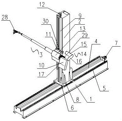
[0024] Such as figure 1 As shown, a pipeline inner wall spraying robot includes a base 1, a column 2 vertically arranged above the base 1, and a multi-section servo electric cylinder 3 vertically arranged on one side of the column 2.
[0025] The top surface of the base 1 is provided with a groove along the middle of its length direction and retains its two end surfaces. A ball screw 4 is connected between the two end surfaces. A linear guide A5 is installed on the upper side, and a freely slidable slider A6 is installed on the linear guide A5. One end of the ball screw 4 is connected with a main motor 7 that drives the ball screw 4, and the main motor 7 is fixedly installed On the end face of the base 1.
[0026] The column 2 is vertically and fixedly connected to the slider A6 of the linear guide A5, the connection between the column 2 and the slider A5 is provided with a reinforcing rib 8, and the column 2 is provided with a middle opening across the side of the linear guide A5 The groove along its height direction and its upper end surface are retained. A lifting ball screw 9 is connected between the upper end surface of the column 2 and the top surface of the slider A6. A linear guide B10 is installed on both sides, a freely slidable slider B11 is installed on the linear guide B10, and a lifting motor 12 that drives the lifting ball screw 9 is installed on the upper end of the lifting ball screw 9, and the lifting The motor 12 is fixed on the upper end surface of the column 2. A Z-axis box 13 is fixed on the slider B11 of the linear guide B10 on the column 2, and the column 2 is connected with a control panel 15 through a connecting piece 14. The connecting piece 14 is in the shape of "┐" and includes a connecting rod 15 and a connecting plate 16 perpendicularly connected to the connecting rod 15. The other end of the connecting plate 16 is connected to the control panel 17, and the other end of the connecting rod 15 is fixedly installed on the column 2. On the side opposite to the installation direction of the spray gun 28.
[0027] Such as figure 2 As shown, the multi-section servo electric cylinder 3 is installed and inserted into the Z-axis box 13, and a motor mounting plate 18 is also provided in the Z-axis box 13, and the multi-section servo electric cylinder 3 includes a servo motor 19, Synchronous wheel 20 and a cylinder structure, the cylinder structure includes a fixed ball screw 21, a ball screw nut 22, a hollow ball screw 23, a cylinder body 24, an output shaft 25, and a terminal output shaft 26, the cylinder The main body 24 and the servo motor 19 are fixedly connected to one side of the motor mounting plate 18 through a screw rod. The synchronization wheel 20 is fixedly connected to the other side of the motor mounting plate 18 through a screw rod and is driven by the servo motor 19. The shaft 25 is sleeved in the cylinder body 24, the end output shaft 26 is sleeved in the output shaft 25, the front end of the output shaft 25 is provided with a connecting plate 27, and a spray gun 28 is installed on the connecting plate 27. A fixed ball screw 21 is coaxially installed in the hollow ball screw 23, the fixed ball screw 21 is inserted into the motor mounting plate 18, and the rear end of the fixed ball screw 21 is connected with an electric cylinder rotary motor 29, so The electric cylinder rotary motor 29 is provided with a motor heat sink 30, the electric cylinder rotary motor 29 is outside the Z-axis housing 13, and the fixed ball screw 21 is sleeved with a floating ball screw 31, the floating ball The screw rod 31 has a hollow structure and its inner hole is a threaded hole matching with the fixed ball screw rod 21, and the ball screw nut 22 is sleeved on the rear end of the floating ball screw rod 31.
[0028] When the servo motor 19 rotates forward, it drives the synchronous wheel 20 to rotate. The hollow ball screw 23 is used as the active shaft to rotate. The splines on the inner wall of the hollow ball screw 23 drive the floating ball screw 31 to rotate. The floating ball screw 31 rotates while rotating. Move along the lead of the fixed rolling screw 21. The floating ball screw 31 rotates and moves linearly, thereby driving the end output shaft 26 to move back and forth, thereby realizing the multi-stage output of the electric cylinder; at the same time, the electric cylinder rotary motor 29 at the rear end of the fixed ball screw 21 can be driven when rotating The multi-section servo electric cylinder 3 rotates to meet the requirements of pipeline spraying; when the servo motor 19 is reversed, the output shafts of the electric cylinder return to the inside of the body according to the lead motion speed of the screw.
[0029] The pipeline inner wall painting robot follows the layout of a Cartesian coordinate robot. The column 2 can move horizontally along the linear guide A5 on the base 1, and the multi-section electric servo cylinder 3 can move up and down along the linear guide B10 on the vertical column 2. The end output shaft 26 of the multi-section electric servo cylinder 3 can move back and forth, thus forming a 4-axis structure. When in use, according to the characteristics of spraying, linear spraying, arc spraying, swing spraying and custom spraying are preset on the control software, and the spraying operation method can be adjusted at any time according to the conditions of the pipeline.
[0030] The basic principles and main features of the present invention and the advantages of the present invention are shown and described above. Those skilled in the industry should understand that the present invention is not limited by the foregoing embodiments. The foregoing embodiments and descriptions only illustrate the principles of the present invention. Without departing from the spirit and scope of the present invention, the present invention will have Various changes and improvements, these changes and improvements all fall within the scope of the claimed invention. The scope of protection claimed by the present invention is defined by the appended claims and their equivalents.

PUM

no PUM

Description & Claims & Application Information

We can also present the details of the Description, Claims and Application information to help users get a comprehensive understanding of the technical details of the patent, such as background art, summary of invention, brief description of drawings, description of embodiments, and other original content. On the other hand, users can also determine the specific scope of protection of the technology through the list of claims; as well as understand the changes in the life cycle of the technology with the presentation of the patent timeline. Login to view more.

Similar technology patents

Classification and recommendation of technical efficacy words

  • Accelerate
  • Run smoothly
Why Eureka
Try Eureka