A cone-shaped shaker distributor

A distributor and cone technology, which is applied in the field of cone shaker distributor, can solve the problems of not being able to meet the needs of blast furnaces, exposure of transmission chains, failure, etc., and achieve the effects of reduced effective height, low production cost, and simple equipment

Active Publication Date: 2018-03-20
僧全松
View PDF9 Cites 0 Cited by
  • Summary
  • Abstract
  • Description
  • Claims
  • Application Information

AI Technical Summary

Problems solved by technology

However, none of them succeeded
The reason is that there is a common problem: the transmission chain is exposed to the furnace head space with extremely harsh working conditions, high temperature, high humidity, high dust, and highly chemically corrosive substances
What the blast furnace needs is equipment that can run stably for a long time without being destroyed or destroyed, otherwise, it will not be able to meet the needs of the blast furnace

Method used


Image

  • A cone-shaped shaker distributor
  • A cone-shaped shaker distributor
  • A cone-shaped shaker distributor

Examples


Embodiment Construction

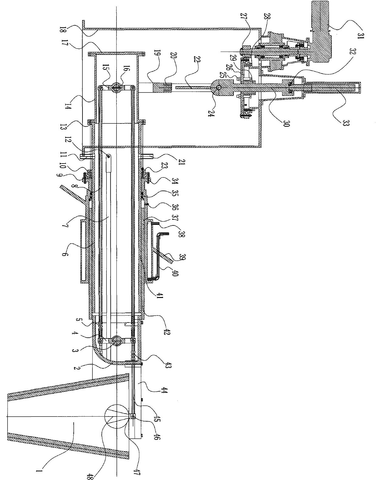
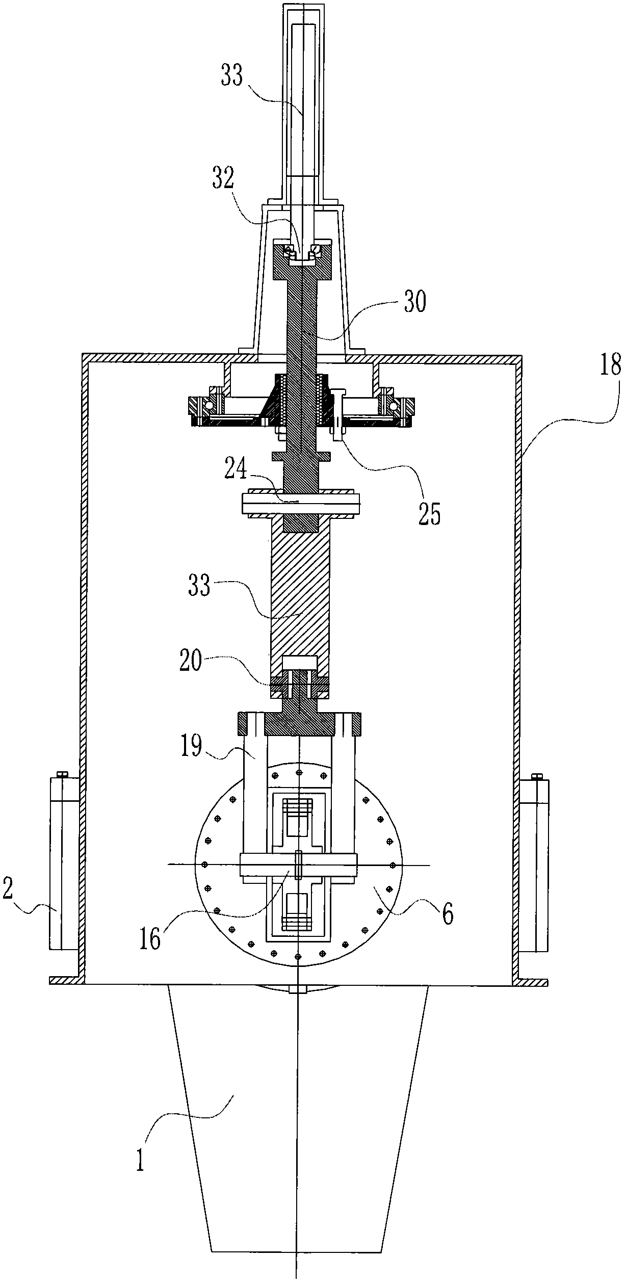
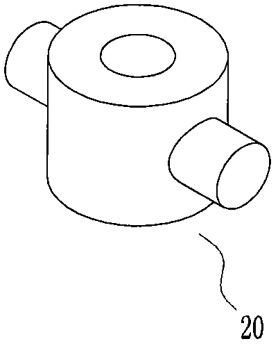
[0029] Such as Figure 1-11 As shown, the reference signs described in the embodiments of the present invention are as follows:

[0030]1 Cone barrel; 2 Hukou frame; 3 Intermediate shaft; 4 Intermediate shaft rocker arm; 5 Tie rod length adjustment bolt; 6 Main shaft; 7 Water inlet pipe; 8 Long tie rod; ;12 Water inlet; 13 Main shaft end flange; 14 Sub shaft box; 15 Sub shaft inner rocker arm; 16 Sub shaft; 17 Sub shaft box cover; 18 Transmission box; 22 crank; 23 main shaft middle flange; 24 transverse shaft; 25 limit bolt; 26 bearing base plate; 27 slewing bearing; 28 slewing bearing seat; Thrust bearing; 33 Oil cylinder; 34 Shaker slewing support seat; 35V seal assembly; 36 Oil cup; 37 Outer ring seal; 38 Drain outlet; Insertion pipe; 43 tie rod length adjustment bolt; 44 tiger mouth frame cover; 45 short tie rod; 46 pin shaft; 47 trunnion rocker arm; 48 trunnion; 51 first driving wheel; 52 first wire rope; Steel wire rope; 55 trunnion sheave; 61 second driving wheel; 62...


PUM


Abstract

The invention relates to a distributing device for a cone shaker, which is composed of a shaker, a cone and a driving device. The shaker is composed of a hollow main shaft, a tiger's mouth frame and an auxiliary shaft box. , The sub-shaft is perpendicular to the main shaft and intersects. The cone is hung on the trunnion. It shakes back and forth with the main shaft and left and right with the trunnion. The trunnion is driven by the sub-shaft. Pulley type, gear transmission shaft type, the transmission mechanism is enclosed in the water-cooled shaking table, there are two driving methods, the mechanical synthesis is the synthesis of rotation and linear motion, the rotation is driven by the slewing bearing with external teeth, and the ball spline linear bearing It is fixed with the big gear, and the push rod is forced to rotate. At the same time, it moves up and down with the oil cylinder to push the crank and the main rocker arm, so that the main shaft, auxiliary shaft and trunnion shake together. There are electric and hydraulic power (hydraulic cylinder and oil motor) , the main shaft driving mechanism is fixed on the furnace head, and the auxiliary shaft driving mechanism is fixed on the main shaft, and the synthetic cloth movement is controlled by automation.

Description

technical field [0001] The invention relates to a distributor for a blast furnace, in particular to a distributor for a conical cylinder shaker. Background technique [0002] Since the beginning of this century, China's ironmaking industry has developed rapidly, with an annual output of more than 600 million tons. It accounts for more than half of the world's output, which is more than the sum of the output of all countries except China, creating a miracle in human history. The main reason for this miracle is the rapid promotion of a new type of charging equipment on the blast furnace - a chute distributor that combines rotation and linear motion. This distributor is the invention of the inventor of the application, Seng Quansong, etc. Patent No.: 85109284.5 "Hydraulic Transmission Distributing Device"; 86104673.0 "Distributing Device"; .1 "Forced feeding throttle valve for blast furnace bellless", etc., referred to as SS (Seng's) type chute distributor, SS (Seng's) type b...

Claims


Application Information

Patent Timeline
Patent Type & Authority Patents(China)
IPC IPC(8): C21B7/20
Inventor 僧全松
Owner 僧全松
Why Eureka
Try Eureka