Location system for ball screw

A ball screw, positioning system technology, applied in the direction of belt/chain/gear, mechanical equipment, transmission device, etc., can solve the problems of slow screw running speed, difficult to meet modern production, low work efficiency, etc., to achieve high precision, Perfect balance of practicality and beautiful appearance

Inactive Publication Date: 2016-11-23
SHENYANG ZHONGTUO ROBOT EQUIP
View PDF0 Cites 2 Cited by
  • Summary
  • Abstract
  • Description
  • Claims
  • Application Information

AI Technical Summary

Problems solved by technology

[0003] Disadvantages of the existing technology: At present, the existing technology is to realize the positive and negative rotation of the lead screw through a motor and electrical control to realize the reciprocating operation of the manipulator connected to the s

Method used


Image

  • Location system for ball screw
  • Location system for ball screw
  • Location system for ball screw

Examples


Embodiment Construction

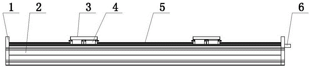
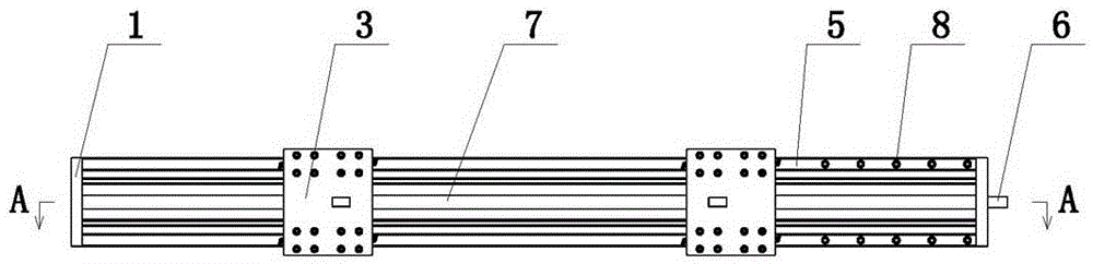
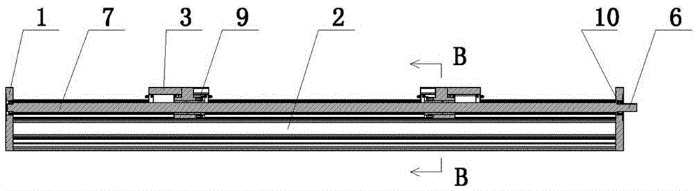
[0015] The present invention includes a load-bearing beam 2, which is characterized in that: a ball screw 7 is arranged inside the load-bearing beam 2, and the two ends of the ball screw 7 are arranged as positive and negative thread structures; A connecting slide 3 is provided.

[0016] As a preferred solution of the present invention, guide rails 5 are provided on both sides of the upper surface of the profile, and sliders 4 that cooperate with the guide rails 5 are provided on the connecting slide 3 .

[0017] Both sides of the upper surface of the load beam 2 are provided with T-shaped grooves 13, and the guide rail 5 is fixed on both sides of the upper surface of the profile through connecting bolts 8 and T-shaped grooves 13, and the upper surface of the load-bearing beam 2 is located between the two T-shaped grooves 13 Screw installation slots 14 are provided, and end plates 1 are provided at both ends of the load beam 2, and support bearings 10 that cooperate with the b...


PUM


Abstract

A ball screw positioning system belongs to the technical field of Cartesian coordinate robots for automatic loading and unloading of automobile stamping parts, and in particular relates to a ball screw positioning system. The invention provides a positioning system which occupies less space and has high working efficiency, in which a lead screw drives a sliding block to move in opposite directions. The present invention includes a load-bearing beam, characterized in that: a ball screw is arranged inside the load-bearing beam, and the two ends of the ball screw are configured as positive and negative thread structures; the two ends of the ball screw are provided with connecting slide plates through screw nuts.

Description

technical field [0001] The invention belongs to the technical field of Cartesian coordinate robots for automatic loading and unloading of automobile stamping parts, and in particular relates to a ball screw positioning system. Background technique [0002] At present, in the field of rectangular coordinate robots, ball screws are also widely used. Ball screw transmission has the advantages of large torque and high precision. [0003] Disadvantages of the prior art: At present, the prior art uses a motor to realize the positive and negative rotation of the lead screw through electrical control to realize the reciprocating operation of the manipulator connected to the screw nut. Due to the limitation of the diameter and lead of the lead screw, the lead screw The running speed of the belt is slower than that of the synchronous belt and the rack, so its work efficiency is low and it is difficult to meet the needs of modern production. Contents of the invention [0004] The pr...

Claims


Application Information

Patent Timeline
IPC IPC(8): F16H25/22
CPCF16H25/2204
Inventor 杨树彬
Owner SHENYANG ZHONGTUO ROBOT EQUIP
Why Eureka
Try Eureka