Balance weight loading device and loading method thereof

A counterweight device and counterweight technology, which is applied in the direction of measuring devices, using stable tension/pressure testing material strength, instruments, etc., can solve problems such as reduced work efficiency, increased test costs, and limited application range of loading test methods. Achieve convenient operation, reduce material and labor costs, and increase load

Pending Publication Date: 2016-11-23
SHANGHAI MUNICIPAL ENG DESIGN INST GRP
View PDF0 Cites 5 Cited by
  • Summary
  • Abstract
  • Description
  • Claims
  • Application Information

AI Technical Summary

Problems solved by technology

[0007] Aiming at the problems that the existing loading test method has limited scope of application and relies on a fixed test site, resulting in reduced work efficiency and increased test cost, the purpose of the present invention is to provide a loading counterweight device and a loading method thereof, which expands the loading reaction The scope of application of the force test makes the loading test safer and more reliable, the selection of the test site is more flexible, and reduces the material and labor costs of the loading test

Method used


Image

  • Balance weight loading device and loading method thereof
  • Balance weight loading device and loading method thereof
  • Balance weight loading device and loading method thereof

Examples


Embodiment 1

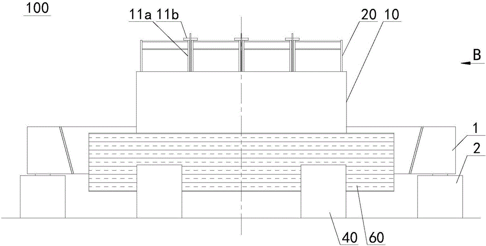
[0028] Example 1: Combining Figure 1 to Figure 3 Illustrate that the loading counterweight device 100 of the present invention is used to carry out the loading test on the test beam 1 placed horizontally on the pier 2 at both ends, and the above-mentioned loading counterweight device 100 includes a reinforced concrete reaction force frame 10, which consists of vertical and A pair of columns 11 oppositely arranged, some tie beams 12 connected to the bottom of the columns 11, spanning and affixed to the code beam 20 at the top of a pair of columns 11, and fixed at the bottom of the code beam 20 and connected to the column 11 parallel auxiliary beams 30;

[0029] The above-mentioned loading counterweight device 100, the reinforced concrete reaction force frame 10 as the main structure is composed of a pair of columns 11 vertically and oppositely arranged and some tie beams 12 connected to the bottom of the columns 11 to form a U-shaped frame, the yard beam 20 and The auxiliary ...

Embodiment 2

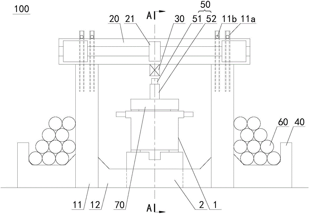
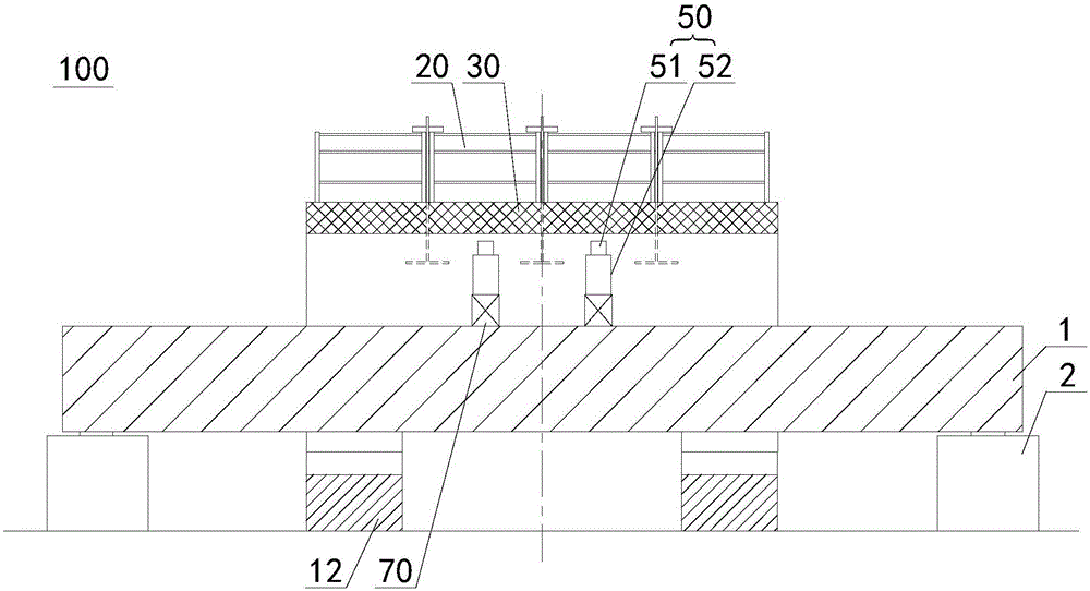
[0035]Embodiment 2: Different from Embodiment 1, the loading counterweight device 100 of this embodiment also includes an anti-jacking device 50 resting on the top of the test beam 1. The above-mentioned anti-jacking device 50 includes a jack 52 and is installed on the top of the jack 52. The pressure sensor 51. Lift the jack 52 to tighten the auxiliary beam 30, and then realize the loading on the test beam 1. In this embodiment, both the jack 52 and the pressure sensor 51 can be purchased through commercial channels.

Embodiment 3

[0036] Example Three: Combining Figure 1 to Figure 3 Illustrate the loading method of the loading counterweight device of the present invention, concrete steps are as follows:

[0037] 1. Lift the test beam 1 and erect it on the pier 2 located on both sides of the test beam 1, and make the test beam 1 between the two columns 11 of the reinforced concrete frame 10;

[0038] 2. Place the reverse jacking device 50 between the test beam 1 and the auxiliary beam 30, and reserve a gap between the reverse jacking device 50 and the auxiliary beam 30;

[0039] Three, start the anti-jacking device 50, load the test beam 1 by the anti-jacking device 50, load the counterweight object 60 to the maximum load once or step by step on the corbel 40 on both sides of the column body 11, and record the corresponding load The data measured by the lower anti-jack device 50.

[0040] In the loading method of the above-mentioned loading counterweight device, at first the test beam 1 is erected bet...


PUM

PropertyMeasurementUnit
diameteraaaaaaaaaa
diameteraaaaaaaaaa

Abstract

The invention relates to a balance weight loading device and a loading method thereof, relating to the technical field of test detection of prefabricated parts. The invention aims at solving the problems that the working efficiency is reduced, and the experimental cost is increased because an existing loading test method has a limited application range and depends on a fixed test site. The balance weight loading device comprises a reinforced concrete weight counter-force frame, wherein the reinforced concrete weight counter-force frame comprises a pair of pillar bodies, a plurality of tie beams, a yard beam, an auxiliary beam and a plurality of brackets, the pillar bodies are vertically and oppositely arranged, the pillar bodies are connected to the bottom ends of the pillar bodies, the yard beam transversely stretches across and fixedly connected to the top ends of the pillar bodies, and the auxiliary beam is fixedly connected to the bottom of the yard beam and is parallel with the pillar bodies; and the brackets are fixedly connected to the outer sides of the pillar bodies. The loading method comprises the following steps: bridging a test beam on buttresses and between two pillar bodies of the reinforced concrete weight counter-force frame; putting a reverse-jacking device between the test beam and the auxiliary beam, and pre-forming a gap between the reverse-jacking device and the auxiliary beam; and applying load to the test beam through the reverse-jacking device, applying the maximum load to balance weight objects at the bracket on two sides of the pillar bodies, and observing and recording data tested by the reverse-jacking device.

Description

technical field [0001] The invention relates to the technical field of test and detection of prefabricated components, in particular to a loading counterweight device and a loading method thereof. Background technique [0002] With the continuous development of bridge engineering standardization and factoryization, there are more and more test and inspection items for prefabricated beams; among them, loading test is one of the important links of bridge static load test, and loading test can make prefabricated beams enter the normal working state. The relationship between structural deformation and load is stable, so as to test the design and construction quality of the bridge. [0003] At present, the commonly used loading test methods include direct surcharge method and anchor pile reverse jacking method, the analysis is as follows: [0004] The direct stacking method is the most commonly used method. Generally, steel ingots or concrete blocks are directly stacked on the p...

Claims


Application Information

Patent Timeline
Patent Type & Authority Applications(China)
IPC IPC(8): G01N3/02G01N3/08
CPCG01N3/02G01N3/08
Inventor 陈明翁思熔卢永成朱立锋
Owner SHANGHAI MUNICIPAL ENG DESIGN INST GRP
Why Eureka
Try Eureka