
A method for testing the accuracy of ct photon counting detectors

A photon counting and detector technology, which is applied in the direction of instrumentation and radiation measurement, to achieve the effect of simple phantom structure, reducing morbidity, and avoiding waste of resources

Active Publication Date: 2018-11-27
NORTHEASTERN UNIV LIAONING
View PDF0 Cites 0 Cited by
  • Summary
  • Abstract
  • Description
  • Claims
  • Application Information

AI Technical Summary

Problems solved by technology

The same point of this design is that the obtained equation will be highly ill-conditioned, and then it will be a difficult problem to obtain the correct discrete energy spectrum value by solving the equation. The existing technology is focused on finding a more effective method for solving the ill-conditioned equation. , such as iterative perturbation method, etc., to obtain more correct discrete energy spectrum values

Method used


Image

  • A method for testing the accuracy of ct photon counting detectors
  • A method for testing the accuracy of ct photon counting detectors
  • A method for testing the accuracy of ct photon counting detectors

Examples


Embodiment Construction

[0031] The specific implementation manners of the present invention will be further described in detail below in conjunction with the accompanying drawings and embodiments. The following examples are used to illustrate the present invention, but are not intended to limit the scope of the present invention.

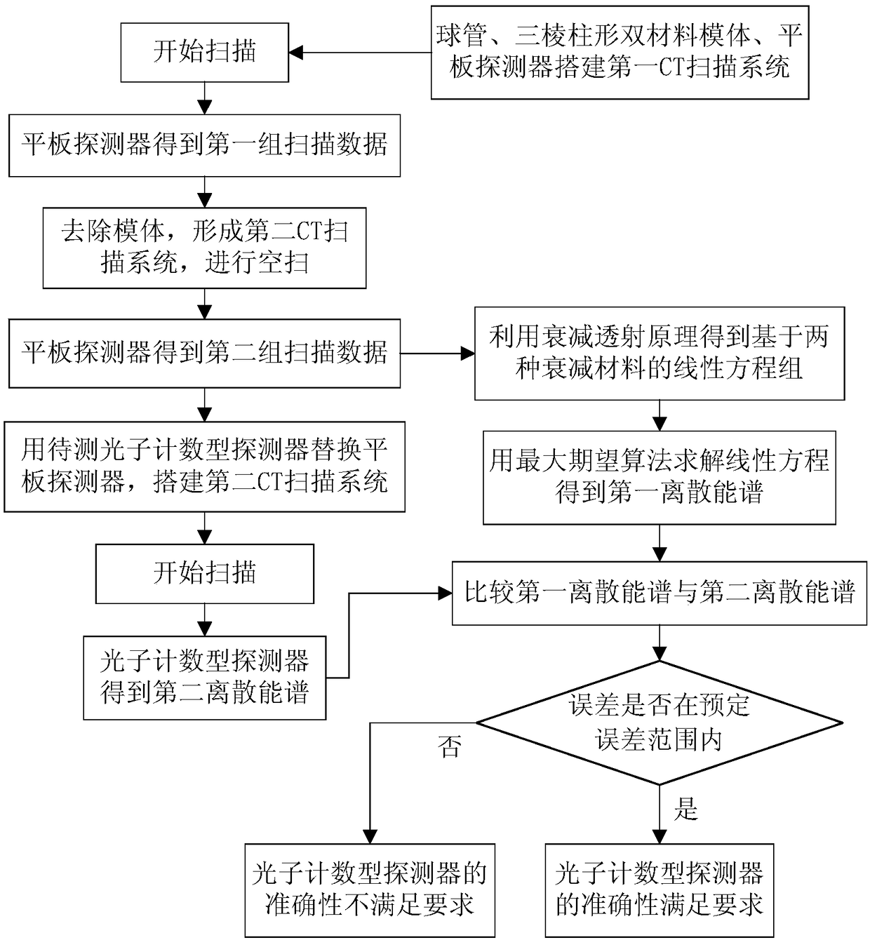
[0032] Such as figure 1 As shown, the method of this embodiment is as follows.

[0033] Step 1. Build the first CT scanning system, including light source 1, phantom 2 and detector 3, such as Figure 4 As shown, scan the phantom 2 to get the first set of scan data I(x s,i ), the specific method is as follows.

[0034] Step 101, setting the light source 1 as an X-ray tube, in this embodiment, the light source 1 is set with a discrete energy spectrum of 10 keV-130 keV;

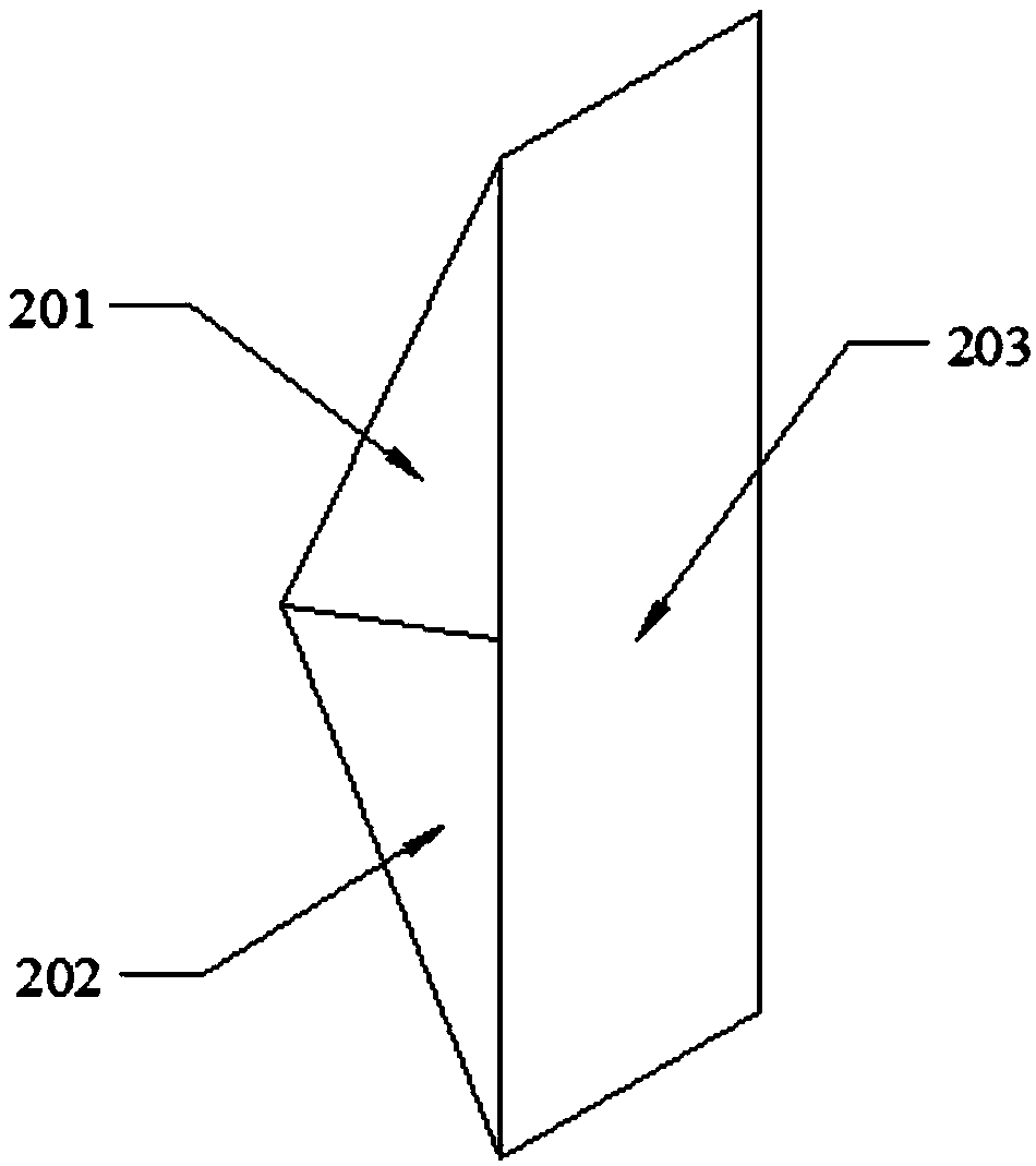
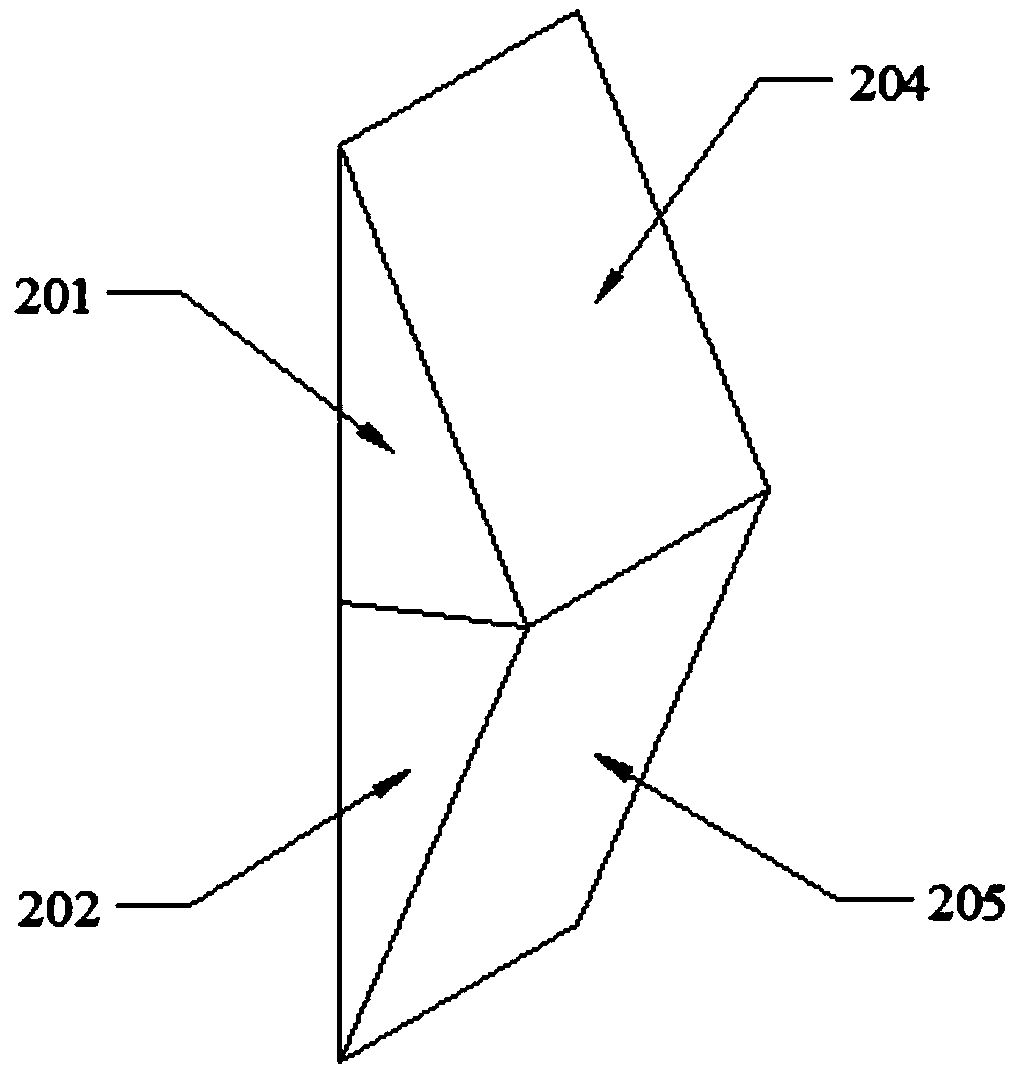
[0035] Step 102, the phantom 2 is set between the light source 1 and the detector 3, and the phantom 2 is set as a triangular prism-shaped dual-material phantom, such as figure 2 As shown, the upper and ...


PUM


Abstract

The invention provides a method for detecting the accuracy of a CT photon counting detector, and relates to the technical field of medical equipment. A CT scanning system was built using an Use the data to construct a system of linear equations and solve to obtain the first discrete energy spectrum of Spectrum, if the error is within a certain range, the accuracy of the photon counting detector meets the requirements. By setting up a triangular prism-shaped dual-material phantom, based on the attenuation transmission principle, the present invention uses two attenuation substances to perform energy spectrum measurement, effectively improving the root cause of the ill-conditioned linear equations to be solved. The phantom structure is simple and the number of scans is small. , effectively avoiding waste of resources and high reliability.

Description

Technical field: [0001] The invention relates to the technical field of medical equipment, in particular to a method for detecting the accuracy of a CT photon counting detector. Background technique: [0002] A typical CT device mainly includes three parts, namely a scanning part, an examination bed, and an operation console. Among them, the CT scanning part is mainly composed of X-ray tubes, high-voltage generators, detectors, data acquisition systems, and control computers. The X-ray tube emits an X-ray beam to scan the selected layer, and the detector converts the collected X-ray signal into an electrical signal, which is converted into a digital signal by an analog / digital (A / D) converter and input to the computer for storage. And processing, so as to obtain the CT value of each unit volume of this layer, and arrange it into a digital matrix. The detector is an important part of the CT system. The traditional charge-integrating X-ray detector does not have the ability ...

Claims


Application Information

Patent Timeline
Patent Type & Authority Patents(China)
IPC IPC(8): G01T7/00
CPCG01T7/005
Inventor 胡静旋刘瑜伽滕月阳赵伟杨金亮董淑艳康雁
Owner NORTHEASTERN UNIV LIAONING
Learn More