High-frequency High-output Device
A high output and equipment technology, applied in the direction of semiconductor/solid-state device parts, semiconductor devices, electrical components, etc., to achieve the effect of relieving stress and preventing cracking
- Summary
- Abstract
- Description
- Claims
- Application Information
AI Technical Summary
Problems solved by technology
Method used
Image

Examples
Embodiment approach 1
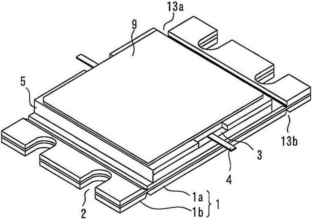
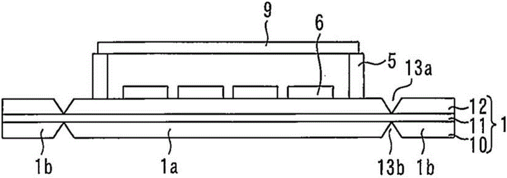
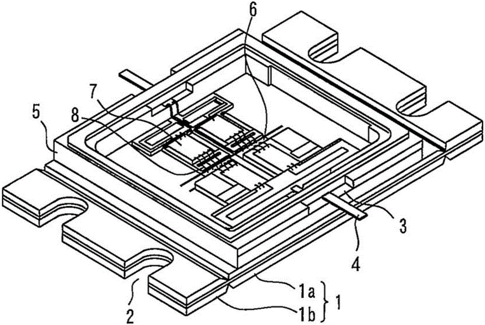
[0029] figure 1 and figure 2 These are a perspective view and a cross-sectional view showing the high-frequency, high-output device according to Embodiment 1 of the present invention, respectively. image 3 and Figure 4 These are a perspective view and a plan view showing the inside of the high-frequency high-output device according to Embodiment 1 of the present invention, respectively.
[0030] The base plate 1 has a mounting portion 1a and a flange portion 1b. The attachment portion 1 a is arranged at the center of the base plate 1 in the longitudinal direction, and the flange portions 1 b are arranged on both sides of the attachment portion 1 a in the longitudinal direction. Notches 2 for inserting screws for fixing the base plate 1 are provided in the flange portion 1b. Here, the notches 2 are respectively provided with more than or equal to 1 place on the opposite short sides of the base plate 1 . In addition, an opening may be used instead of the notch 2 .
[00...
Embodiment approach 2
[0040] Figure 9It is a cross-sectional view showing a high-frequency high-output device according to Embodiment 2 of the present invention. In this embodiment, the V-groove 13 a is provided only on the upper surface of the base plate 1 between the mounting portion 1 a and the flange portion 1 b of the base plate 1 . The V-groove 13a is provided in the Cu plate 12, and its depth may or may not reach the Mo plate 11. In addition, the shape of the V-groove 13a may be a U-shape, a concave shape, etc., and the shape is not limited. Since the flange part 1b is easy to bend starting from this V-groove 13a, the same effect as Embodiment 1 can be acquired.
Embodiment approach 3
[0042] Figure 10 It is a cross-sectional view showing a high-frequency high-output device according to Embodiment 3 of the present invention. In the present embodiment, V-grooves 13 a and 13 b are provided at vertically different positions on the upper surface and the lower surface of the base plate 1 between the mounting portion 1 a and the flange portion 1 b of the base plate 1 . The V-grooves 13a and 13b are provided on the Cu plates 10 and 12, respectively, and the depth thereof may or may not reach the Mo plate 11. In addition, the shape of the V-grooves 13a and 13b may be a U-shape, a concave shape, etc., and the shape is not limited.
[0043] Since the flange part 1b is easy to bend starting from these V-grooves 13a and 13b, the same effect as Embodiment 1 can be acquired. In addition, by providing the V-grooves 13a and 13b at positions different from each other up and down on the upper surface and the lower surface of the base plate 1, it is possible to perform opti...
PUM
 Abstract
Description
Claims
Application Information
 - R&D
- Intellectual Property
- Life Sciences
- Materials
- Tech Scout
- Unparalleled Data Quality
- Higher Quality Content
- 60% Fewer Hallucinations
Browse by: Latest US Patents, China's latest patents, Technical Efficacy Thesaurus, Application Domain, Technology Topic, Popular Technical Reports.
© 2025 PatSnap. All rights reserved.Legal|Privacy policy|Modern Slavery Act Transparency Statement|Sitemap|About US| Contact US: help@patsnap.com