Electrically controlled magnetic energy high-efficient motor

A technology of electric control and magnetic energy, which is applied in the field of high-efficiency electric motor structure with electric control and magnetic energy, can solve problems such as laborious, small driving force attraction, and low-efficiency driving methods, and achieve the goals of eliminating urban smog, improving motor efficiency, and increasing mileage Effect

Inactive Publication Date: 2016-11-23
高林
View PDF0 Cites 1 Cited by
  • Summary
  • Abstract
  • Description
  • Claims
  • Application Information

AI Technical Summary

Problems solved by technology

[0002] A simple fact, if two permanent magnets are attracted together, it will take a lot of effort to pull them apart in the longitudinal direction (suction direction); if they are moved tangentially, it will save a lot of effort
However, the permanent magnet motors used at the present stage are driven by the tangential attraction between the electromagnet and the permanent magnet to generate rotation. The driving force generated is much smaller than the longitudinal attraction, and the magnetic potential energy of the permanent magnet is not fully utilized to participate in the work. A very inefficient way to drive

Method used


Image

  • Electrically controlled magnetic energy high-efficient motor
  • Electrically controlled magnetic energy high-efficient motor

Examples


Embodiment Construction

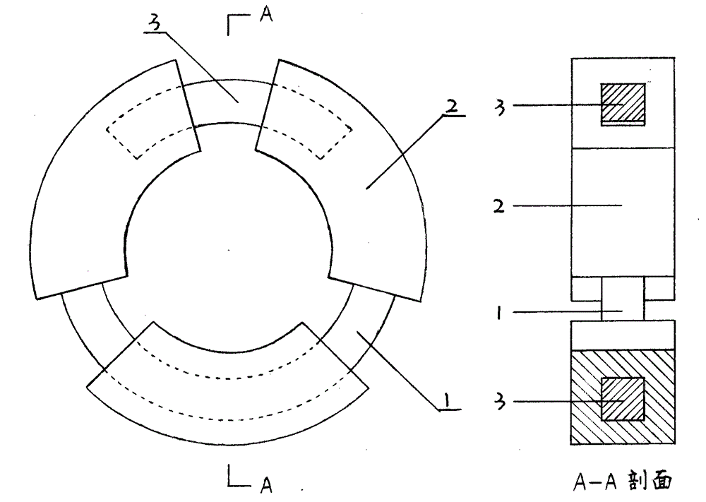
[0020] The electronically controlled magnetic energy high-efficiency motor involved in the present invention only discloses a basic structure and driving mode, and the specific structures of the electronically controlled magnetic energy efficient motor designed and manufactured using it are varied. This embodiment only provides a schematic diagram of its basic structure, and the specific structures are various, which do not constitute a limitation to the present invention.

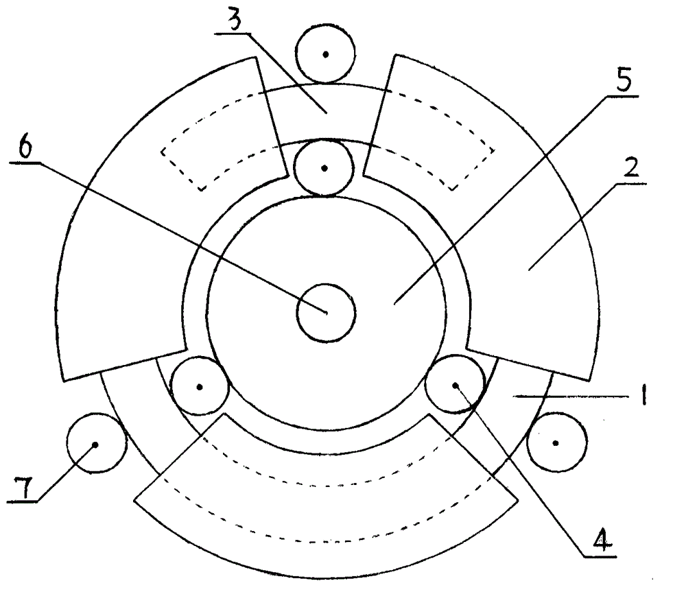
[0021] figure 2 Among them, a gear drive plate is installed on the inner ring surface of the annular rotor (1) (the figure is only for illustration, not realistic), the electromagnetic control coil (2) is fixed on the casing as the stator, and the shaft of the intermediate transmission wheel (4) and The output shaft (6) is fixed on the casing through bearings, and the three intermediate transmission wheels (4) also play the role of limiting the inner ring surface of the annular rotor (1), preventing it fr...


PUM


Abstract

The invention discloses an electrically controlled magnetic energy high-efficient motor. Longitudinal attraction force of a solenoid electromagnetic control coil and a permanent magnet is converted into driving force of the motor, and magnetic potential energy of the permanent magnet is effectively utilized to participate in working, so that the efficiency of the motor is greatly improved. A good electrically controlled magnetic energy high-efficient motor is designed. When the same electric power is input, the driving force can be improved by over 4 times by the electrically controlled magnetic energy high-efficient motor in comparison with an existing permanent magnet motor. The electrically controlled magnetic energy high-efficient motor can be used as a traction motor (the traction motor can be directly used and can also be transformed into a linear motor) of an aircraft carrier electromagnetic launcher, and a propulsion motor of a submarine in military, is especially suitable for being used as a drive motor of an electric vehicle in the field of civil, replaces the existing permanent magnet motor in the increasingly serious energy crisis and environmental pollution today, and can play roles in energy conservation and emission reduction. Meanwhile, the electrical vehicle has economy and practicability, can be really popularized and comes into the homes of common people, and a contribution is made to removing urban haze.

Description

technical field [0001] The invention relates to the manufacture of electric motors in the field of electricity, in particular to an electric control magnetic energy high-efficiency motor structure utilizing the magnetic potential energy of permanent magnets through electromagnetic control. Background technique [0002] A simple fact, if two permanent magnets are attracted together, it will take a lot of effort to pull them apart in the longitudinal direction (direction of suction force); if they are moved tangentially, it will save a lot of effort. However, the permanent magnet motors used at this stage all use the tangential attraction between the electromagnet and the permanent magnet to generate rotation. The driving force generated is much smaller than the attraction along the longitudinal direction, and the magnetic potential energy of the permanent magnet is not fully utilized to participate in the work. A very inefficient way of driving. Making full use of the magnet...

Claims


Application Information

Patent Timeline
Patent Type & Authority Applications(China)
IPC IPC(8): H02K1/27H02K3/00
CPCY02T10/64
Inventor 高林
Owner 高林
Why Eureka
Try Eureka