Motor capable of directly driving rotating shaft

A rotary axis, direct technology, applied in the field of CNC machine tools, can solve problems such as the lack of positioning accuracy, and achieve the effect of small radial size, large torque and high speed

Inactive Publication Date: 2016-11-23
郑先道
View PDF3 Cites 0 Cited by
  • Summary
  • Abstract
  • Description
  • Claims
  • Application Information

AI Technical Summary

Problems solved by technology

Because the motor needs to achieve safe power output and precise mechanical positioning in a limited installation space during application, and the existing motors

Method used


Image

  • Motor capable of directly driving rotating shaft

Examples


example 1

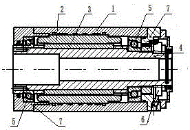
[0024] see figure 1 , the motor includes a motor casing 1, and the motor casing is provided with a motor stator 2, a motor rotor 3 and a hollow shaft 4 sequentially from outside to inside; the two ends of the hollow shaft pass through a screw bearing 5 respectively, and each screw bearing passes through the end The cover 7 is fixed with the hollow shaft, and the encoder 6 is fixed at one end of the hollow shaft.

[0025] The motor housing is cylindrical.

[0026] When in use, after the motor is energized, the rotor drives the hollow shaft to rotate, the hollow shaft is equipped with an encoder, the encoder rotates, and the reading head outputs measurement signals. The motor drive system controls the precise movement of the motor based on the measured feedback signal.


PUM


Abstract

The invention provides a motor capable of directly driving a rotating shaft, and aims to solve the problem that when an existing motor is used, safe power output and accurate mechanical positioning cannot be implemented in limited mounting space. According to the technical scheme, the motor comprises a motor shell, wherein a motor stator, a motor rotor and a hollow shaft are successively arranged in the motor shell from outside to inside; lead screw bearings respectively penetrate through two ends of the hollow shaft; each lead screw bearing and the hollow shaft are fixed together through an end cap; and an encoder is fixed at one end of the hollow shaft. The motor capable of directly driving the rotating shaft has the advantages of simple structure, simplicity and convenience in operation, high reliability and high feasibility.

Description

technical field [0001] The invention belongs to the technical field of numerical control machine tools, in particular to a motor capable of directly driving a rotating shaft. Background technique [0002] As an electromechanical product, the motor has deeply penetrated into every corner of people's daily life, but in some specific occasions, the existing motor cannot meet the needs of production and life due to its structural limitations. [0003] For example, in the field of machine tools, the turret parts of armored vehicles and tanks in the military industry are usually processed by large floor boring machines, or by large special machines, which require huge equipment and large investment. If a machine tool with a CNC cutter head and a feed axis is used for processing, the equipment investment is small and the adaptability is wide. Another example is the machining of the two-axis head of the automobile axle housing assembly, which is usually processed on a double-head l...

Claims


Application Information

Patent Timeline
IPC IPC(8): H02K7/08H02K11/20
CPCH02K7/08
Inventor 郑先道王海
Owner 郑先道
Why Eureka
Try Eureka