
Control information sending method and device

A technology for controlling information and sending methods, applied in the direction of forward error control, signaling allocation, transmission path sub-channel allocation, etc., can solve problems such as inability to indicate wider transmission parameters and transmission schemes, and inability to support transmission assumption requirements

Active Publication Date: 2016-11-23
ZTE CORP
View PDF5 Cites 49 Cited by
  • Summary
  • Abstract
  • Description
  • Claims
  • Application Information

AI Technical Summary

Problems solved by technology

[0012] The present invention provides a method and device for sending control information to at least solve the problem that CQI or downlink control information (DCI for short) cannot indicate wider transmission parameters and transmission schemes in the related art, and CQI definitions cannot support new Technical issues such as transmission assumption requirements

Method used


Image

  • Control information sending method and device
  • Control information sending method and device
  • Control information sending method and device

Examples


Embodiment 1

[0154] In this embodiment, it is assumed that the control information is UCI, the first transmission node is the receiving side, and the second transmission node is the sending side. Including the following two sub-embodiments.

Embodiment 11

[0155] Sub-embodiment 1.1: the first transmission node sends control information to the second transmission node, where the above-mentioned control information includes an indication information. The above indication information is used to indicate the interleaving parameters. In this embodiment, the interleaving parameter is the interleaving depth. The above-mentioned interleaving depth includes four levels, which respectively correspond to the interleaving of data on the number of X1 / X2 / X3 OFDM symbols in the time domain. That is to say, the sending side obtains several code block data after encoding and modulation, and the data between code blocks are interleaved and mapped to time domain resources, so that the data of one code block can be distributed to X1 / X2 / X3 OFDM symbols to gain time diversity gain. Alternatively, the interleaving depth includes two levels, which respectively correspond to the interleaving of data on X4 / X5 subcarriers in the frequency domain. That ...

Embodiment 12

[0158] Sub-embodiment 1.2: the first transmission node sends control information to the second transmission node, where the above-mentioned control information includes indication information. The above indication information is used to indicate selection indication information of an interleaving mode. In this embodiment, the interleaving mode includes time / frequency / code block interleaving. The interleaving method indicated by the control information reflects the method of obtaining potential diversity gain and matches the channel variation. Help the sending side to process data, so that the sent data can obtain time-frequency domain gain and improve system performance.


PUM


Abstract

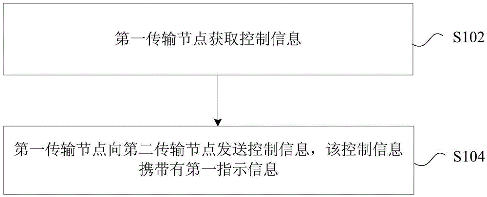
The invention provides a control information sending method and device. The method comprises the following step: a first transmission node sends control information to a second transmission node, wherein the control information carries first indication information, the first indication information being used for indicating at least one of the following items: interleaving parameters, interleaving mode selection indication information, code block segmentation parameters, code block segmentation method selection indication information, CRC parameters, CRC adding method selection indication information, baseband pulse shaping filter parameters, filtering method selection indication information, a first kind of parameters, a second kind of parameters and joint encoding of the first kind of parameters and the second kind of parameters. Through the technical scheme, the control information sending method and device solve the problems that CQI or DCI cannot indicate wider transmission parameters and transmission scheme, and definition of CQI cannot support a new transmission hypothesis, thereby supporting self-adaptive transmission of the system, improving system throughput and meeting different service requirements.

Description

technical field [0001] The present invention relates to the field of mobile wireless communication, in particular to a method and device for sending control information. Background technique [0002] In the mobile communication system, due to the time-varying characteristics of the wireless fading channel, there are a lot of uncertainties in the communication process. In this way, when the signal-to-noise ratio of the wireless fading channel is relatively ideal, the system throughput has indeed been greatly improved, but when the channel is in deep fading, it cannot guarantee reliable and stable communication. On the other hand, in order to ensure the reliability of communication , using low-order modulation with a low transmission rate and large redundant error-correcting codes for communication, that is, to ensure reliable and stable communication when the wireless channel is in deep fading. However, when the channel signal-to-noise ratio is high, due to the low transmissi...

Claims


Application Information

Patent Timeline
IPC IPC(8): H04L5/00H04L1/00
CPCH04L1/0071H04L5/0057
Inventor 陈泽为徐俊袁志锋李儒岳
Owner ZTE CORP
Learn More